
- Normal:
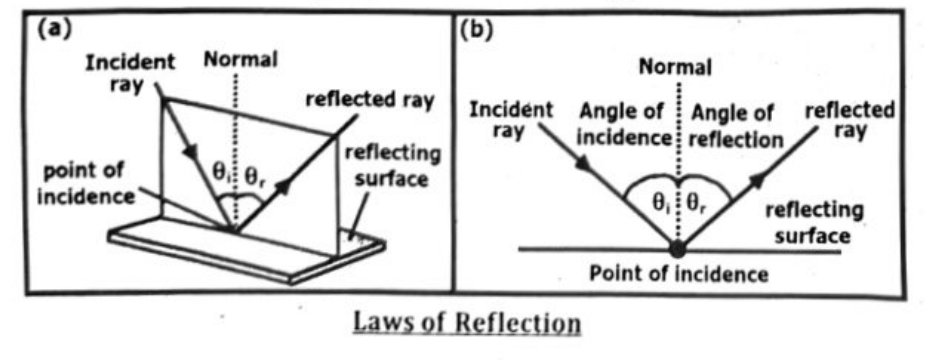
Definition: The normal is an imaginary line drawn perpendicular (at $90^\circ$) to the surface at the point where the incident ray strikes it.
Usage:
- It serves as a crucial reference line for measuring angles. It is always drawn as a dashed or dotted line on ray diagrams to distinguish it from actual light rays.
- Even if the surface is curved, the normal is drawn perpendicular to the tangent of the curve at the point of incidence.
- Angle of Incidence ($\theta_i$):
Definition: The angle of incidence is the angle between the incident ray (the incoming ray of light or wave) and the normal at the point of incidence.
Usage: This angle determines how the light or wave hits the surface.
- It is always measured with respect to the normal, not the surface itself.
- If a ray hits the surface perpendicularly (straight on), the angle of incidence is $0^\circ$ (because the ray is aligned with the normal).
- Angle of Reflection ($\theta_r$):
Definition: The angle of reflection is the angle between the reflected ray (the ray of light or wave that bounces off the surface) and the normal at the point of incidence.
Usage:
- This angle describes the direction in which the light or wave bounces off the surface.
- Similar to the angle of incidence, it is always measured with respect to the normal.
- The Law of Reflection states that for specular (mirror-like) reflection, the angle of incidence is equal to the angle of reflection ($\theta_i = \theta_r$).
REFLECTION OF LIGHT
“When a ray of light approaches a smooth polished surface and bounces back is called reflection.”
Reflection of light is the bouncing back of light rays when they hit a surface, changing their direction. This occurs because the surface doesn't absorb the light energy but instead sends it back into the same medium. The type of reflection depends on the surface's smoothness: smooth surfaces like mirrors cause regular reflection, while rough surfaces cause diffuse reflection.
EXPLANATION
(i) The Basics
- When light travels and encounters a surface, it can be absorbed, transmitted, or reflected.
- Reflection occurs when light bounces back into the same medium after hitting a surface.
- This is similar to how a ball bounces off a wall.
(ii) Types of Reflection
- Regular Reflection (Specular Reflection): Occurs when light reflects off a smooth, polished surface like a mirror, and the reflected rays travel in a parallel manner.
- Diffuse Reflection: Occurs when light reflects off a rough surface, and the reflected rays scatter in different directions. This is how we see objects – light from a source is reflected off an object and enters our eyes.
(iii) Key Concepts
- Incident Ray: The light ray that approaches the surface.
- Reflected Ray: The light ray that bounces off the surface.
- Normal: A line perpendicular to the surface at the point where the incident ray strikes.
- Angle of Incidence: The angle between the incident ray and the normal.
- Angle of Reflection: The angle between the reflected ray and the normal.
(iv) Laws of Reflection
- The angle of incidence is always equal to the angle of reflection.
- The incident ray, the reflected ray, and the normal all lie in the same plane.
(v) Examples
- Seeing your reflection in a mirror (regular reflection).
- Seeing the light from a lamp reflected off a wall (diffuse reflection).
- Normal:
Definition: The normal is an imaginary line drawn perpendicular (at $90^\circ$) to the surface at the point where the incident ray strikes it.
Usage:
- It serves as a crucial reference line for measuring angles. It is always drawn as a dashed or dotted line on ray diagrams to distinguish it from actual light rays.
- Even if the surface is curved, the normal is drawn perpendicular to the tangent of the curve at the point of incidence.
- Angle of Incidence ($\theta_i$):
Definition: The angle of incidence is the angle between the incident ray (the incoming ray of light or wave) and the normal at the point of incidence.
Usage: This angle determines how the light or wave hits the surface.
- It is always measured with respect to the normal, not the surface itself.
- If a ray hits the surface perpendicularly (straight on), the angle of incidence is $0^\circ$ (because the ray is aligned with the normal).
- Angle of Reflection ($\theta_r$):
Definition: The angle of reflection is the angle between the reflected ray (the ray of light or wave that bounces off the surface) and the normal at the point of incidence.
Usage:
- This angle describes the direction in which the light or wave bounces off the surface.
- Similar to the angle of incidence, it is always measured with respect to the normal.
- The Law of Reflection states that for specular (mirror-like) reflection, the angle of incidence is equal to the angle of reflection ($\theta_i = \theta_r$).
REFLECTION OF LIGHT
“When a ray of light approaches a smooth polished surface and bounces back is called reflection.”
Reflection of light is the bouncing back of light rays when they hit a surface, changing their direction. This occurs because the surface doesn’t absorb the light energy but instead sends it back into the same medium. The type of reflection depends on the surface’s smoothness: smooth surfaces like mirrors cause regular reflection, while rough surfaces cause diffuse reflection.
EXPLANATION
(i) The Basics
- When light travels and encounters a surface, it can be absorbed, transmitted, or reflected.
- Reflection occurs when light bounces back into the same medium after hitting a surface.
- This is similar to how a ball bounces off a wall.
(ii) Types of Reflection
- Regular Reflection (Specular Reflection): Occurs when light reflects off a smooth, polished surface like a mirror, and the reflected rays travel in a parallel manner.
- Diffuse Reflection: Occurs when light reflects off a rough surface, and the reflected rays scatter in different directions. This is how we see objects – light from a source is reflected off an object and enters our eyes.
(iii) Key Concepts
- Incident Ray: The light ray that approaches the surface.
- Reflected Ray: The light ray that bounces off the surface.
- Normal: A line perpendicular to the surface at the point where the incident ray strikes.
- Angle of Incidence: The angle between the incident ray and the normal.
- Angle of Reflection: The angle between the reflected ray and the normal.
(iv) Laws of Reflection
- The angle of incidence is always equal to the angle of reflection.
- The incident ray, the reflected ray, and the normal all lie in the same plane.
(v) Examples
- Seeing your reflection in a mirror (regular reflection).
- Seeing the light from a lamp reflected off a wall (diffuse reflection).
Image Formation by plane Mirrors:
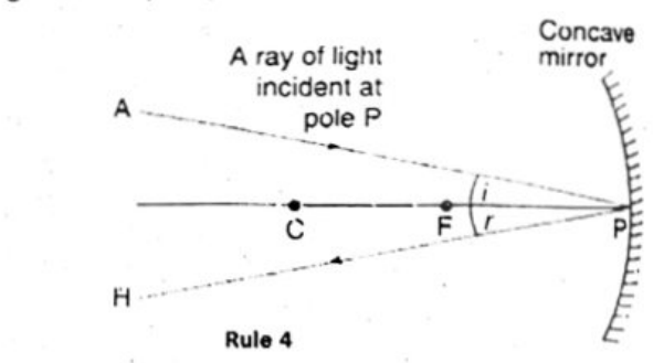
- When a ray strikes concave or convex mirrors obliquely at its pole, it is reflected obliquely making the same angle with the principal axis.
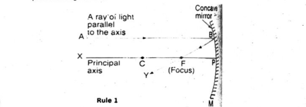
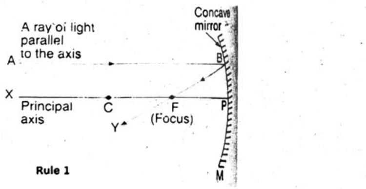
- When a ray, parallel to the principal axis strikes concave or convex mirrors, the reflected ray passes through the focus on the principal axis.
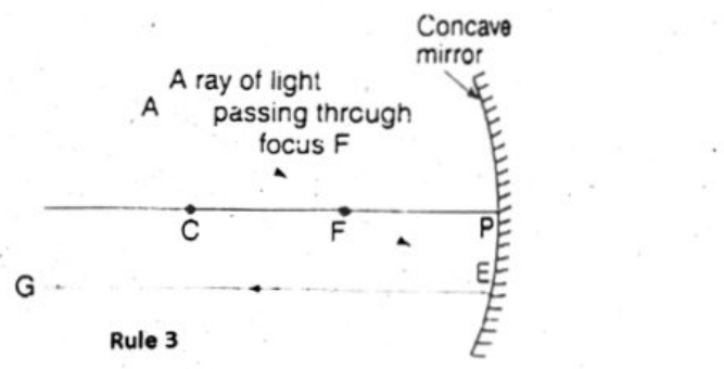
- When a ray, passing through focus strikes concave or convex mirrors, the reflected ray will be parallel to the principal axis.
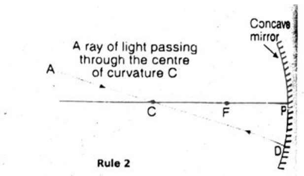
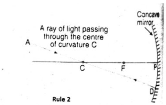
- A ray passing through the centre of curvature of the spherical mirror will retrace its path after reflection.
Ray diagram to form image by concave mirror
Rules for obtaining images formed by concave mirror:
- Rule 1:
When a ray of light which is parallel to the principal axis gets reflected, it passes through its focus.
- Rule 2:
When a ray of light passes through the centre of curvature, it gets reflected back along the same path.
Rule 3: When a ray of light passes through the focus, it becomes parallel to the principal axis after reflection.
Rule 4: A ray of light which is incident at the pole is reflected back making the same angle with the principal axis.
Ray diagram to form image by convex mirror:
Rules for obtaining images formed by convex mirror:
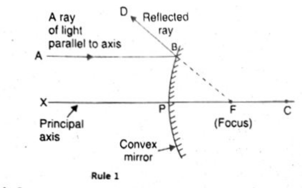
- Rule 1: After reflection, a ray of light parallel to the principal axis appears to be coming from focus.
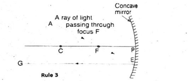
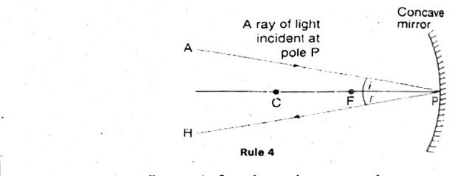
Image Formation by plane Mirrors:
- When a ray strikes concave or convex mirrors obliquely at its pole, it is reflected obliquely making the same angle with the principal axis.
- When a ray, parallel to the principal axis strikes concave or convex mirrors, the reflected ray passes through the focus on the principal axis.
- When a ray, passing through focus strikes concave or convex mirrors, the reflected ray will be parallel to the principal axis.
- A ray passing through the centre of curvature of the spherical mirror will retrace its path after reflection.
Ray diagram to form image by concave mirror:
Rules for obtaining images formed by concave mirror:
- Rule 1:
When a ray of light which is parallel to the principal axis gets reflected, it passes through its focus.
- Rule 2:
When a ray of light passes through the centre of curvature, it gets reflected back along the same path.
- Rule 3: When a ray of light passes through the focus, it becomes parallel to the principal axis after reflection.
- Rule 4: A ray of light which is incident at the pole is reflected back making the same angle with the principal axis.
Ray diagram to form image by convex mirror:
Rules for obtaining images formed by convex mirror:
- Rule 1: After reflection, a ray of light parallel to the principal axis appears to be coming from focus.
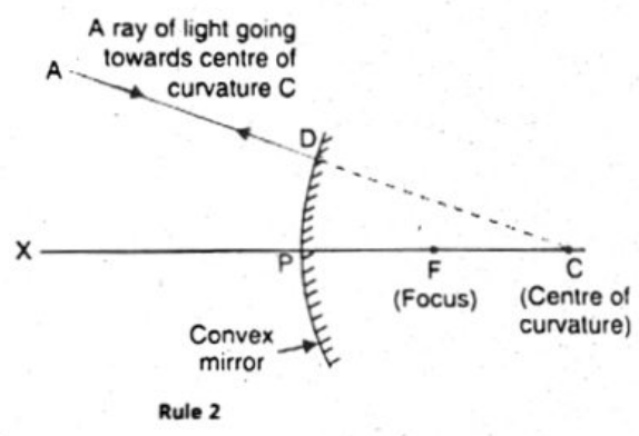
- Rule 2: A ray of light going towards centre of curvature is reflected back along the same path.
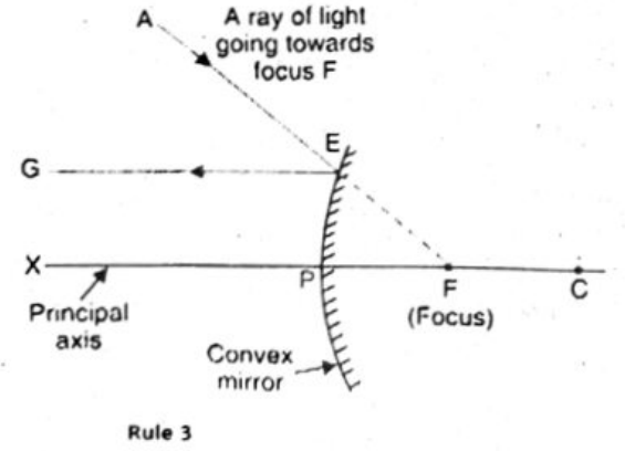
- Rule 3: After reflection, a ray of light going towards the focus becomes parallel to the principal axis.
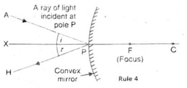
Rule 4: Ray of light which is incident at the pole is reflected back making the same angle with the principal axis.
Characteristics of an optical image formed by a plane mirror:
A plane mirror forms a virtual, upright, laterally inverted image that is the same size as the object and at the same distance behind the mirror.
Here’s a more detailed breakdown:
- Virtual: The image appears to be behind the mirror, but no light rays actually converge there. It’s an optical illusion.
- Upright: The image is oriented the same way as the object; it’s not upside down.
- Laterally Inverted: The image is reversed left to right. This is why a “left” looks like a “right” in the mirror.
- Same Size: The image has the same dimensions as the object.
- Same Distance: The distance between the image and the mirror is equal to the distance between the object and the mirror.
Law of reflection:
The law of reflection states that the angle of incidence (the angle between the incoming light ray and the normal, a line perpendicular to the surface) is equal to the angle of reflection (the angle between the outgoing light ray and the normal). This principle is used to solve various optical problems by determining the path of reflected light rays.
Simple Optical Problems with the Law of Reflection:
(I) A ray of light strikes a plane mirror at an angle of incidence of 40°. What is the angle of reflection?
Solution:
Angle of incidence (θi) = 40°
According to the Law of Reflection, θi = θr.
Calculate the angle of reflection:
Since, θi = 40°. Then, θr = 40°.
The angle of reflection is 40°.
(II) A ray of light strikes a mirror along the normal (angle of incidence = 0°). What will be the angle of reflection?
Solution:
Angle of incidence = 0°
According to the Law of Reflection: θi = θr = 0°.
The ray reflects straight back. Angle of reflection is 0°.
- Normal: The normal is an imaginary line drawn at 90° (perpendicular) to the surface where the light ray hits. It is used as a reference to measure angles of light rays.
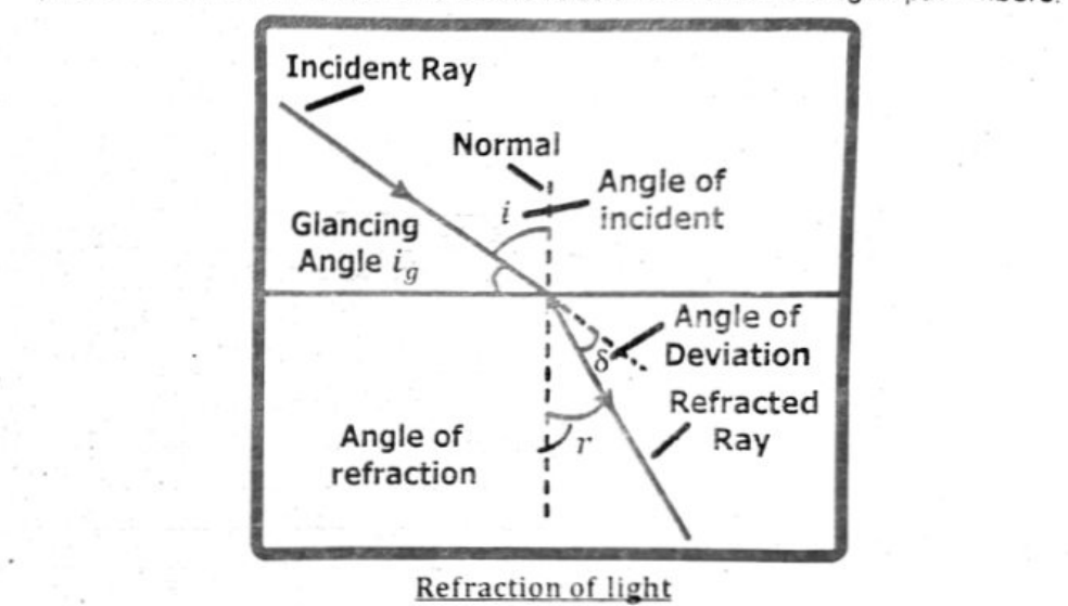
- Angle of incidence: The angle of incidence is the angle between the incident ray (the incoming ray of light) and the normal at the point where the light enters the surface.
- Angle of refraction: The angle of refraction is the angle between the refracted ray (the ray that bends inside the new material) and the normal at the point where the light passes into the new medium.
Laws of Reflection:
There are two laws which govern the reflection of light as:
- The incident ray, the reflected ray, and the normal all lie in the same plane.
- The angle of incidence ‘θi’ and angle of reflection ‘θr’ are equal. This can be represented mathematically as: θi = θr.
When light bounces between two mirrors facing each other, it creates multiple reflections. For instance, in a barber shop, you can see a series of your images due to the reflections between the front and back mirrors as shown.
Difference between regular and diffused reflection:
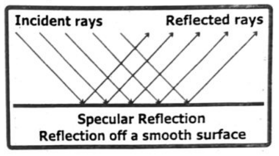
Regular or specular reflection:
This occurs on smooth surfaces like mirrors, where the reflection is clear and sharp. The angles of reflection are consistent across the surface leading to a distinct image being formed.
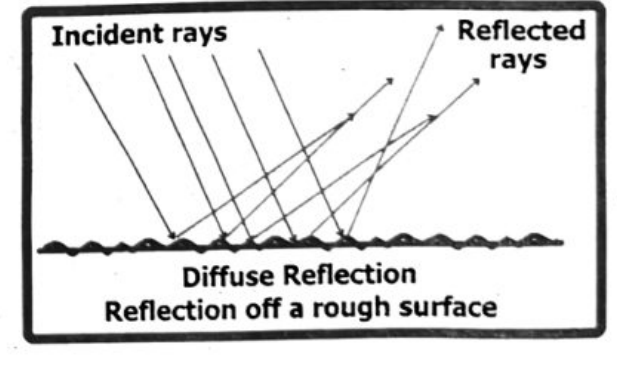
Diffused reflection:
This happens on rough surfaces where the reflected rays scatter in many directions. This type of reflection allows us to see most non-shiny objects like this page of your book that is why you can see this page from all sides not from only at a single point the diffused reflection of light and image from many sides is shown in figure.
When a wave travels from one medium to another, its speed can change, causing it to refract (bend). If the wave slows down, it bends towards the normal (an imaginary line perpendicular to the boundary), and if it speeds up, it bends away from the normal. This happens because the wave’s direction changes to maintain a consistent phase relationship across the boundary.
Here's a more detailed explanation:
Refraction and Speed Change:
Refraction occurs when a wave encounters a boundary between two media with different properties, causing a change in the wave's speed.
Bending Towards the Normal:
When a wave slows down as it enters a new medium, it will bend towards the normal. This is because one side of the wave front will be traveling slower than the other, causing the wave to pivot and bend towards the slower side.
Bending Away from the Normal:
Conversely, when a wave speeds up as it enters a new medium, it will bend away from the normal. This happens because the faster side of the wave front will move ahead of the slower side, causing the wave to pivot and bend away from the faster side.
Optically Dense vs. Rarer Media:
Denser media generally slow down waves, while rarer media allow waves to travel faster. Therefore, light bending towards the normal is associated with denser media, and bending away from the normal with rarer media.
Examples:
- Light traveling from air into water slows down and bends towards the normal.
- Light traveling from water into air speeds up and bends away from the normal.
- Water waves traveling from deep water to shallow water slow down and bend towards the normal.
Refraction of light:
“The changing of a light ray’s direction when it passes through variations in matter is called refraction”.
For example if you dip a straight pencil into the glass water such that the full length of pencil does not sink into the water you would observe that the pencil is not straight but it is bended or broken which is known as broken pencil illusion. This is because the light coming from the water to us changes direction when it leaves the water and enters into the air. In this case the light has to travel two different paths to get to our eyes. Refraction is responsible for a tremendous range of optical phenomenon from the action of lenses to voice transmission through optical fibers.
The refractive index of a medium is the ratio of the speed of light in a vacuum to the speed of light in that medium. It tells us how much light slows down when it enters the medium.
It is given by the formula: $n = \frac{c}{v}$
- $n$ = refractive index of the medium
- $c$ = speed of light in vacuum = $3 \times 10^8\ \mathrm{m\ s^{-1}}$
- $v$ = speed of light in the medium = $2.25 \times 10^8\ \mathrm{m\ s^{-1}}$
Therefore, $n = \frac{3 \times 10^8\ \mathrm{m\ s^{-1}}}{2.25 \times 10^8\ \mathrm{m\ s^{-1}}} = 1.33$.
The refractive index of the medium is 1.33. This value is approximately the refractive index of water, indicating that light travels 1.33 times slower in this medium than it does in a vacuum.
REFRACTIVE INDEX:
“The measure of bending of a light ray when passing from one medium to another is called refractive index such that one medium is vacuum”.
It can also be defined as the ratio of the velocity of a light ray in an empty space to the velocity of light in a substance. If ‘c’ is the velocity of light in vacuum and the ‘V’ is the velocity of light in some medium then the refracted index ‘n’ of that medium can be given as:
$n = \frac{c}{v}$
| Medium | Refractive index (n) |
|---|---|
| Air | 1.000293 |
| Carbon dioxide | 1.00045 |
| Oxygen | 1.000271 |
| Benzene | 1.501 |
| Glycerin | 1.473 |
| Water | 1.333 |
| Diamond | 2.419 |
| Polystyrene | 1.49 |
| Glass (crown) | 1.52 |
| Glass (flint) | 1.66 |
| Ice | 1.309 |
| Zircon | 1.923 |
Refractive Index:
The refractive index (n) of a medium is a dimensionless quantity that quantifies how much light slows down when it enters that medium from a
speed of light in that specific medium ($v$).It is given by the formula:
$$n=\frac{\sin(i)}{\sin(r)}$$
Snell’s Law:
Snell’s Law relates the angles and refractive indices of two media:
$$n_i\sin(i)=n_r\sin(r)$$
Simple Problem:
Light enters from air ($n_i=1.00$) into glass ($n_r=1.50$). If the angle of incidence is $i=30^\circ$, find the angle of refraction $r$.
Solution:
$$\begin{aligned}n_i\sin(i)&=n_r\sin(r)\\1.00\times\sin(30^\circ)&=1.50\times\sin(r)\\0.5&=1.5\times\sin(r)\\\sin(r)&=0.5/1.5=0.333\\r&=\sin^{-1}(0.333)\approx19.5^\circ\end{aligned}$$
SCIENCE TIDBITS
If the light enters from one medium to another medium perpendicular to the surface which divides the media then the angle of incident becomes zero. As in this case the light is incident parallel to the normal then Snell’s law will give the angle of refraction also to be zero as:
$$n_1\sin\theta_i=n_2\sin\theta_r;\qquad \text{As, }\sin 0=0$$
As, $0=n_2\sin\theta_r$ and $\theta_r=\sin^{-1}0$
Finally, $\theta_r=0$
This shows that whenever light enters from one medium to another at right angle, whatever their refractive indices may be, the angle of refraction will be zero, i.e. the light does not bend in such situations.
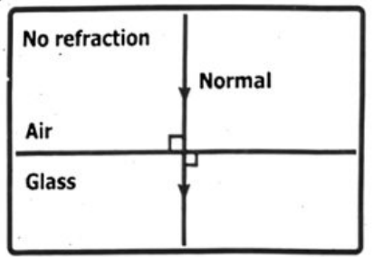
LAWS OF REFRACTION (Snell’s Law):
- The first law states that the incident ray of light, the normal and the refracted ray of light all lie in the same plane.
- The second law is about the relationship between the angles and the indices of refraction of the two media. It can be mathematically given as: $$n_1\sin\theta_i=n_2\sin\theta_r$$
Here ‘$n_1$’ and ‘$n_2$’ are the refractive indices of the two media and ‘$\theta_i$’ is the angle of incident and ‘$\theta_r$’ is the angle of refraction. The same relation can also be written as:
$$\frac{n_1}{n_2}=\frac{\sin\theta_r}{\sin\theta_i}$$
If one of the two media is vacuum, and light enters from vacuum to some medium then ‘$n_1=1$’ and relation reduces to:
$$\frac{1}{n_2}=\frac{\sin\theta_r}{\sin\theta_i}\quad\text{or simply}\quad\frac{1}{n}=\frac{\sin\theta_r}{\sin\theta_i}$$
When light enters into vacuum from some medium then ‘$n_2=1$’ and relation becomes:
$$n_1=\frac{\sin\theta_r}{\sin\theta_i}\quad\text{or simply}\quad n=\frac{\sin\theta_r}{\sin\theta_i}$$
EXPERIMENT TO STUDY REFRACTION:
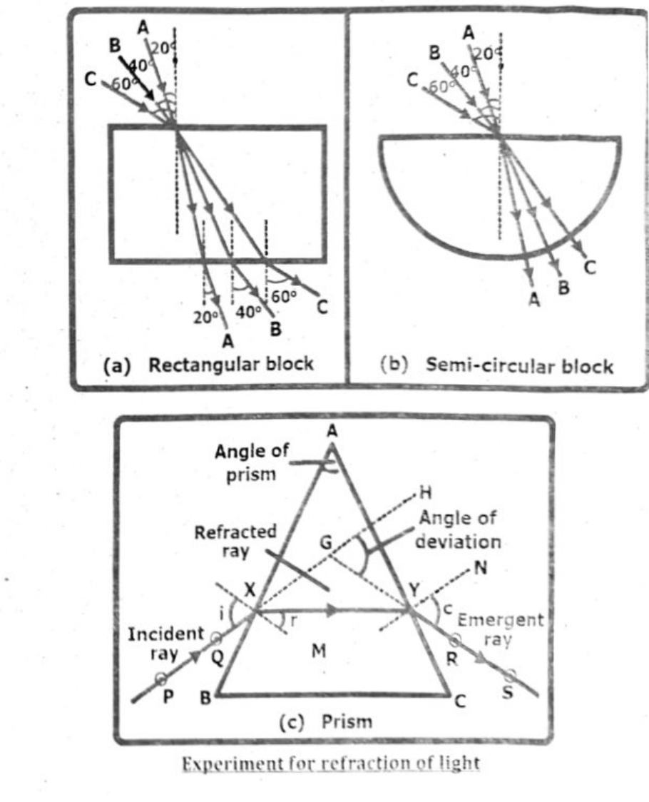
To study the refraction due to transparent blocks of different shapes we can devise an experiment even in our classroom or lab in the school.
- Aim of the Experiment: To study the refraction of light using a rectangular block, semi-circular block and triangular prism made of glass.
- Equipment required: Laser light, protractor, sheet of paper, pencil, ruler and perspex blocks (rectangular, semicircular and prism).
- Method for studying refraction: Place the glass rectangular block on the paper and draw lines around it. Now draw the perpendicular lines which are called as normal. Illuminate one plane side of the block, making some angle with the normal already drawn on the paper.
Mark the following and carefully make observations:
- A point on the paper near the light source.
- A point where the light ray enters into the block.
- The point where the light ray exits the block.
- Another point along the path of the exit light ray at a distance of, say, 4 to 5 cm.
- Remove the light source and the block and join the points marked on the paper sheet with straight lines.
- Replace the block again and repeat the above experiment for some different angles like 20°, 40° and 60°, etc., for the semi-circular block too.
Now take another paper sheet and perform the same experiment for the semi-circular block with three different angles and finally for a glass prism. All three are illustrated in figures (a), (b) and (c).
Because at each point the radial path of the ray is perpendicular to the tangent, the light rays are leaving the block along the normal line and hence suffer no refraction.
(d) Results:
Consider the light paths for different shaped blocks.
- The final diagram for each shape will include multiple light ray paths for the different angles of incidence (i) at which the light strikes the blocks.
- This will help to demonstrate how the angle of refraction (r) changes with the angle of incidence.
- Label these paths for the first two blocks as ‘A’, ‘B’ and ‘C’ to make the paths clear.
- Incident and refracted angles are always measured from the normal.
- In all the cases you would observe that:
- The light entering the block bends towards the normal line, hence: (i > r).
- For light rays exiting the Perspex blocks, all the light rays refract away from the normal line, hence: (i < r).
- For light rays entering along the normal, the light ray does not refract, i.e. it passes straight through the block, and hence: (i = r).
Critical Angle and Total Internal Reflection:
Critical Angle:
The critical angle is the smallest angle of incidence in a denser medium at which the refracted ray just grazes along the boundary between the two media (i.e. the angle of refraction is 90°). It only occurs when light travels from a denser medium to a rarer (less dense) medium (e.g., from glass to air).
Total Internal Reflection:
Total internal reflection is the phenomenon where an entire ray of light, traveling in an optically denser medium, is completely reflected back into the same denser medium when it strikes the boundary with a less dense medium.
From Snell's Law:
$$n_1\sin(i)=n_2\sin(r)$$
Now, consider a light ray going from a denser medium (like glass) with refractive index $n$ into a rarer medium (like air) with refractive index 1 (since the refractive index of air $\approx 1$).
At the critical angle $c$, the angle of refraction $r=90^\circ$.
$$n\sin(c)=1\times\sin 90^\circ\quad\Rightarrow\quad n\sin(c)=1\quad\Rightarrow\quad n=\frac{1}{\sin c}$$
Problem 1:
The critical angle for a transparent material is $30^\circ$. Find the refractive index of the material.
$$n=\frac{1}{\sin 30^\circ}\quad\Rightarrow\quad n=\frac{1}{0.5}\quad\Rightarrow\quad n=2$$
Problem 2:
The critical angle for a material is $45^\circ$. What its refractive index?
$$n=\frac{1}{\sin 45^\circ}\quad\Rightarrow\quad n=\frac{1}{0.7071}\quad\Rightarrow\quad n\approx1.41$$
TOTAL INTERNAL REFLECTION:
“Total internal reflection is the phenomenon of reflection of light ray back to the same medium when passing from denser medium to rarer medium in such a way that angle of incidence is greater than its critical angle.”
Critical angle:
“The angle of incidence for which the angle of refraction is 90° degrees is called as the critical angle.”
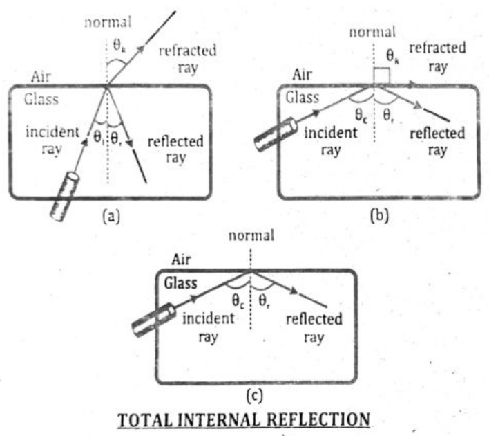
The critical angle is represented by ‘$\theta_c$’. When the angle of incidence of the light ray becomes greater than the critical angle the refracted light ray also reflects back into the same medium from the boundary of two media. At this stage there is no more refraction of light and is known as the total internal reflection of light.
TOTAL INTERNAL REFLECTION
DERIVATION:
To derive a relation for the total internal reflection we use Snell's law:
$$n_1\sin\theta_i=n_2\sin\theta_r$$
As for total internal reflection the refracted angle becomes $90^\circ$, hence the above equation gets the form:
$$n_1\sin\theta_i=n_2\qquad\text{as }\sin 90^\circ=1$$
The sine of critical angle for the given combination of materials:
$$\sin\theta_c=\frac{n_2}{n_1}\qquad\text{(i)}$$
The critical angle can be found as:
$$\theta_c=\sin^{-1}\left(\frac{n_2}{n_1}\right)$$
As we know that the trigonometric ratio of sine can have values maximum up to 1, for this it is necessary that the refractive index of first medium (from
which light ray is incident) should be greater than the refractive index of the second medium (in which light ray is entering), i.e. total internal reflection can only be happened if light ray (travels from denser medium into the lighter medium. If the second medium is air, we can take the refractive index of air unity as ‘$n_2=1$’, then ‘$n_1=n$’ and equation (i) becomes:
$$\sin\theta_c=\frac{1}{n}$$
And in general refractive index of the denser material can be given as:
$$n=\frac{1}{\sin\theta_c}$$
The above relation holds good only if light is entering from any denser medium having refractive index ‘$n$’ into the air.
EXPERIMENT TO STUDY TOTAL INTERNAL REFLECTION:
To study the total internal reflection due to transparent block of semi-circular shape we can device an experiment even in our classroom or lab in the school.
- Aim of the Experiment: To study the total internal reflection of light using a semi-circular block of glass.
- Equipment required: Laser light, protractor, sheet of paper, pencil, ruler and perspex block.
- Method for studying reflection: Place the semi-circular glass block on the paper draw lines around it. Now draw the perpendicular line which is called as normal. Illuminate one plane side of the semi-circular block making some angle with the normal already drawn on the paper. Make the following carefully:
- A point on the paper near the light source
- A point where the light ray enters into the block
- The point where the light ray exits the block
- Another point along the path of exit light ray at a distance of say 4 to 5 cm.
- Move the light source slowly such that the angle of incidence keeps on increasing.
While moving the light source the angle of incident increases which in turn increases the angle of refraction until the refracted line makes an angle of 90° with the normal this incident angle is called as ‘critical angle’. Now mark two points for incoming ray at this stage.
- Results: Consider the light paths for different angles and draw lines. These lines give the following results about the phenomenon of refraction and reflection as:
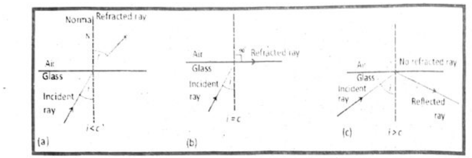
- In the case when the incidence angle was less than the critical angle we noticed the phenomenon of refraction and light entered into the lighter medium from the semi-circular glass block: $i<c$.
- For the case when the incidence angle was equal to that of the critical angle we noticed the refracted light made an angle of 90° with the normal and traveled on the boundary between the two media: $i=c$.
- For the case when the incidence angle was greater than the critical angle we noticed the phenomenon of total internal reflection and light bounced back to the same block in spite of going into the lighter medium from the semi-circular glass block: $i>c$.
Now increase the incidence angle further; the refracted light now enters back into the same semicircular block in spite of going into the other medium. This phenomenon is known as total internal reflection.
Optical fibers are thin strands of glass or plastic that carry light signals using total internal reflection, where light bounces inside without escaping. Optical fibers are widely used in telecommunications for transmitting data as light signals, offering significant advantages over traditional copper wires due to their high bandwidth, long-distance capabilities & resistance to interference. This makes them ideal for high-speed internet, telephone networks, and cable television.
Advantages in Telecommunications:
High Bandwidth and Speed:
Optical fibers can carry significantly more data than copper wires, enabling faster internet speeds and higher capacity for voice and video transmission.
Long Distance Transmission with Minimal Loss:
Light signals experience less attenuation (signal degradation) over long distances, reducing the need for repeaters and boosters compared to copper cables.
Immunity to Electromagnetic Interference (EMI):
Optical fibers are not susceptible to electromagnetic interference, ensuring reliable data transmission in environments with electrical noise.
Security:
Fiber optic cables are more difficult to tap into without detection, enhancing data security compared to traditional copper cables.
Durability and Size:
Fiber optic cables are lighter, thinner, and stronger than copper cables, making them easier to install and manage.
Examples of Use in Telecommunications:
Internet:
Fiber optic cables are the backbone of modern high-speed internet infrastructure, providing the bandwidth needed for streaming, online gaming, and other data-intensive applications.
Telephone Networks:
Optical fibers have replaced copper wires in many telephone networks, enabling high-quality voice communication and facilitating the transition to digital voice transmission.
Cable Television:
Optical fibers carry high-definition television signals and other video content to homes, offering a superior viewing experience with greater bandwidth and clarity.
In essence, optical fibers have revolutionized telecommunications by offering a more efficient, reliable, and secure way to transmit data over long distances, driving the demand for high-speed broadband and advanced communication services, according to telecom industry blogs.
OPTICAL FIBERS:
Optical fiber is a technology that transmits data as light pulses through thin strands of glass or plastic. These strands, known as optical fibers, act as waveguides, guiding light signals over long distances with high bandwidth, making them ideal for high-speed data transmission in communication networks.
Optical fiber is the technology associated with data transmission using light pulses travelling along with a long fiber which is usually made of plastic or glass. The optical fibers use the application of total internal reflection of light.
Optical fiber consists of two concentric tubes of glass or plastic such that the inner tube called the “core” has higher refractive index (having larger density) as compared to the outer tube called the “cladding” with low refractive index (having smaller density). The whole setup is covered for protection by some material called “jacket”. The light enters into the core at an angle greater than the critical angle of the core material, moves within the core by successive total internal reflections. Optical fibers have applications in many fields of life but the most commonly used application of optical fibers is their role in modern telecommunications.
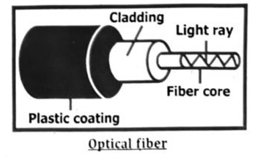
Advantages of optical fiber over copper based network infrastructure:
High band width:
Optical fibers provide significantly higher band width compared to copper wires, where band width is the data transfer capacity of a network in bits per second. In modern times we need a lot of data from our internet at very high speed hence larger bandwidth of optical fibers serves the best to our requirement
Faster Speed:
They can transmit data at faster speeds due to the use of light pulses instead of electrical signals. They transfer the data from one place to another at the speed of light
Resistance to electrical interference:
As we use light in optical fibers hence the electrical interference has no effect on the data as it was a major problem in copper-network transmissions
Long Distance:
It can transmit data over much longer distances without significant signal loss like under-sea cables and inter-continental connections.
Low Power:
They consume less power than copper cables and their durability and longevity reduces maintenance costs.
Optical fibers are used in various sectors, including healthcare, defense, manufacturing, broadcasting, lighting, and communications. In telecommunications, they are essential for data transmission, offering greater speed and accuracy than copper wires.
Optical fiber cables are lighter, more flexible, and can carry more data. Data is converted into a light signal using transducers like LEDs or laser diodes and introduced into the fiber’s core at an angle greater than the critical angle as shown in figure.
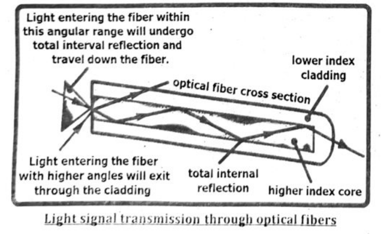
This light signal travels through the optical fibers for long distances until it reaches the destination. At the receiving end, the light signal is converted into an electrical signal with the help of transducers like photodiode, PIN diode or avalanche diode. These diodes convert the light signal into an electrical signal near the user end, and the electrical signal is finally converted into text, voice or video data as required.
Thin Converging Lens (Convex Lens):
- Action: A thin converging lens bends (refracts) parallel rays of light toward a single point called the principal focus.
- Result: The rays meet (converge) after passing through the lens.
- Use: Converging lenses are used in magnifying glasses, cameras, and the human eye.
Thin Diverging Lens (Concave Lens):
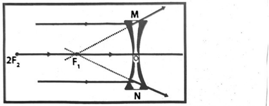
- Action: A thin diverging lens spreads out parallel rays of light as if they are coming from a single point called the principal focus (on the same side as the light source).
- Result: The rays diverge after passing through the lens, and they appear to come from a virtual focus.
- Use: Diverging lenses are used in glasses for short-sighted people and peepholes in doors.
Principal Axis:
- Definition: The principal axis is an imaginary straight line that passes through the center of the lens or mirror and its principal focus.
- Use: It helps us draw accurate ray diagrams and locate the position of the image formed by lenses or mirrors.
Principal Focus (Focal Point):
- Definition: The principal focus is the point where parallel rays of light either meet (in a converging lens or mirror) or appear to come from (in a diverging lens or mirror) after passing through or reflecting.
- Use: The principal focus is used to determine how a lens or mirror bends light and forms images.
Focal Length (f):
- Definition: The focal length is the distance between the center of the lens or mirror and the principal focus.
- Use: The focal length tells us how strong or powerful a lens or mirror is. A shorter focal length means the lens bends light more sharply.
Lenses are transparent optical devices, typically made of glass or plastic, that refract (bend) light to either converge or diverge light rays, thus forming images. They are essential components in various optical instruments like cameras, telescopes, microscopes, and eyeglasses.
Properties and Functions:
Refraction:
Lenses work by bending light as it passes through them, a phenomenon called refraction. This bending occurs because light travels at different speeds in different materials (like air and glass).
Converging (Convex) Lenses:
These lenses are thicker in the middle than at the edges and cause parallel light rays to converge (come together) at a focal point.
Diverging (Concave) Lenses:
These lenses are thinner in the middle than at the edges and cause parallel light rays to spread out (diverge).
Focal Point:
The point where converging light rays meet after passing through a lens, or the apparent point from which diverging rays originate.
Focal Length:
The distance between the center of the lens and the focal point.
Image Formation:
Lenses can form both real (projected on a screen) and virtual (seen by looking through the lens) images.
Types of Lenses and Applications:
Convex (Converging) Lenses:
Used in magnifying glasses, cameras, and to correct farsightedness.
Concave (Diverging) Lenses:
Used to correct nearsightedness.
Compound Lenses:
Combinations of multiple lenses to achieve specific optical effects and correct for aberrations (distortions).
- Fresnel Lenses: Used in lighthouses and other applications where a wide beam of light is needed.
In essence, lenses manipulate light to help us see the world around us, whether it’s through a camera lens capturing a moment, a telescope revealing distant galaxies, or eyeglasses correcting our vision.
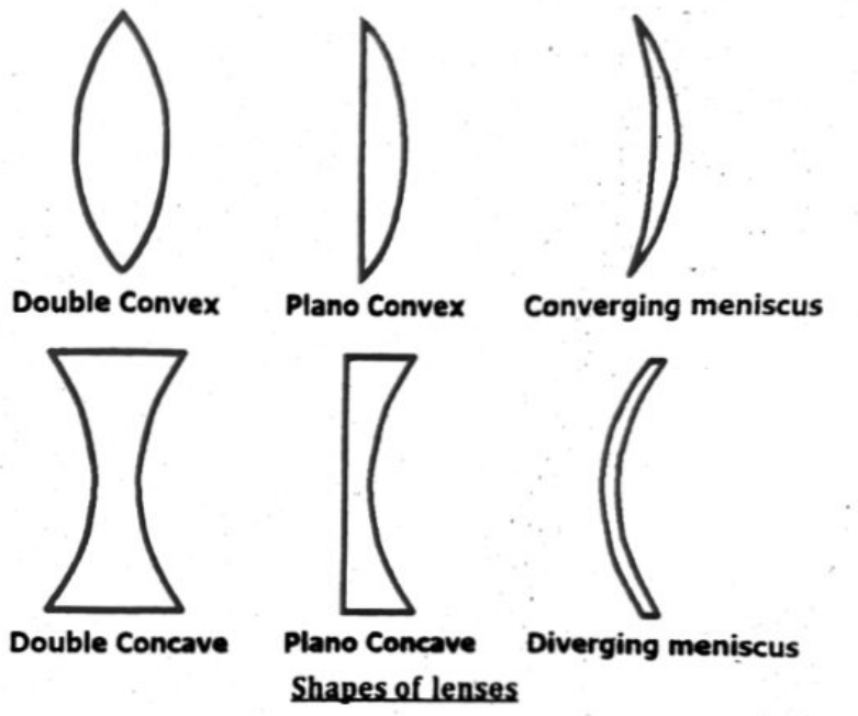
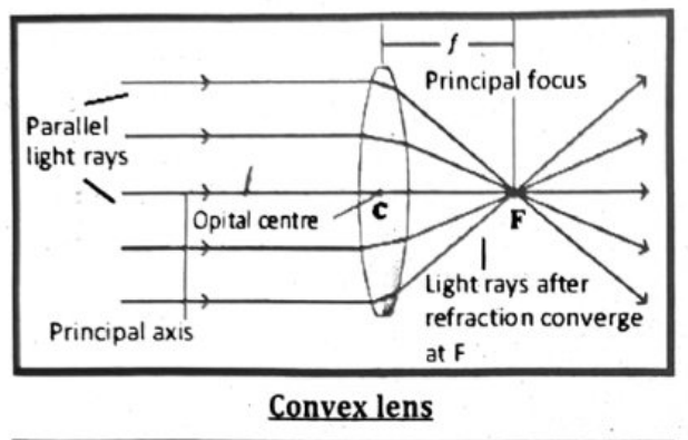
Focal Length:
The distance between the optical center of a lens and its principal focus. It’s essentially the measure of how strongly a lens converges or diverges light.
Principal Axis:
A straight line passing through the centers of curvature of the lens surfaces and the optical center. It’s the central axis of symmetry for the lens.
Principle Focus (Focal Point):
The point on the principal axis where parallel rays of light converge (for a converging lens) or appear to diverge from (for a diverging lens) after passing through the lens.
Optical Centre:
The central point of a lens through which light rays pass without deviation.
Centre of Curvature:
The center of the sphere from which the curved surface of the lens is a part. A lens has two centers of curvature, one for each surface.
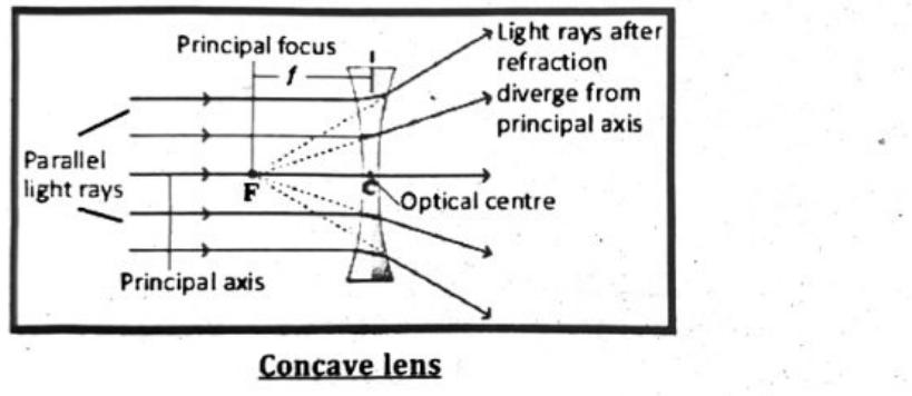
ACTION OF LENSES ON PARALLEL RAYS:
When we strike parallel light rays to a lens these light rays after refraction from the lens show a fascinating pattern. Upon the behavior of a lens to the parallel light rays lenses are classified as converging and diverging lenses.
Converging Lens:
Convergence lens is thicker at its center and thinner at the edges. When a parallel beam of light passes through a thin converging lens (convex lens) the lens refracts the light rays and converges them to a point known as focal point on the other side of the lens. The key characteristics of this process can be given as:
Refraction and Convergence:
The parallel rays are bent towards the principal axis of the lens due to refraction. The curvature and the refractive index of the lens material cause this bending. After passing through the lens all the parallel rays converge at a single point on the principle axis that is the focal point of the lens.
Formation of Image:
The formation of image from the lens depends upon the location of the lens. The image from the converging is normally real and inverted but in some cases it may be virtual image. The behavior of converging lens towards the parallel light rays is shown in figure.
ii. Diverging Lens:
Divergence lens is thinner at its center and thicker at the edges. When a parallel beam of light passes through a thin diverging lens (concave lens) the lens refracts the light rays and diverges them as if they are coming from a point known as the focal point on the same side of the lens from which the light is coming the characteristics of this process are:
Refraction and Divergence:
The parallel rays are bent away from the principle axis of the lens due to refraction. This divergence gives the impression that the rays are emanating from a focal point behind the lens.
Virtual Focal Point:
The focal point for a concave lens is virtual because the light rays do not actually converge there instead they appear to be diverging from this point when extended backward.
Formation of Image:
If an object is placed at infinity the image formed by the diverging lens will be at its virtual focal point and the image will be virtual, upright and diminished. The divergence of parallel light rays from a divergence lens is shown in figure.
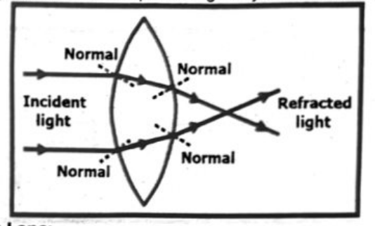
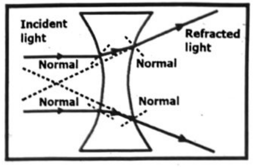
Image Formation in Convex Lens:
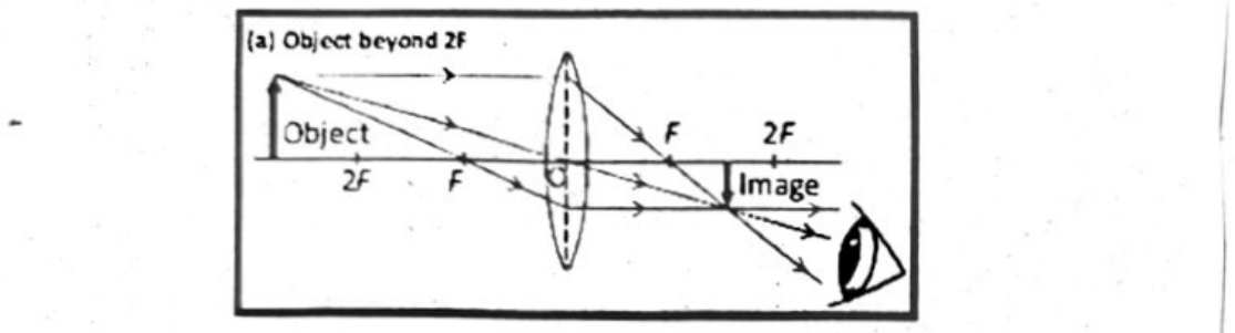
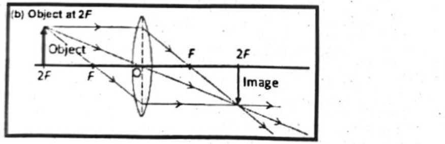
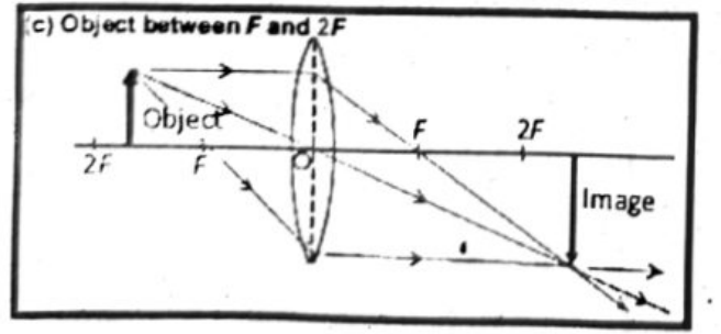
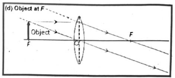
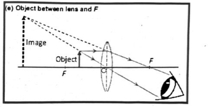
Now we explain image formation with ray diagrams for objects placed at different positions from a convex lens as shown in Fig.
(a) Object Beyond 2F:
The image is between F and 2F, real, inverted, smaller than the object.
(b) Object at 2F:
The image is at 2F, real, inverted, the same size as the object.
(c) Object Between F and 2F:
The image is beyond 2F, real, inverted, larger than the object.
(d) Object at F:
No image is formed because the refracted rays are parallel and never meet.
(e) Object Between Lens and F:
The image is behind the object, virtual, erect, larger than the object.
Image formation by Convex Lens
| Object location | Image location | Image nature | Image size |
|---|---|---|---|
| Infinity | At F2 | Real and Inverted | Diminished, point sized |
| Beyond 2F1 | Between 2F2 and F2 | Real and Inverted | Diminished |
| Between 2F1 and F1 | Beyond 2F2 | Real and Inverted | Enlarged |
| At F1 | At infinity | Real and Inverted | Infinitely large or highly enlarged |
| At 2F1 | At 2F2 | Real and Inverted | Same size |
| Between F1 and O | On the same side as the object | Virtual and Erect | Enlarged |
Concave Lenses:
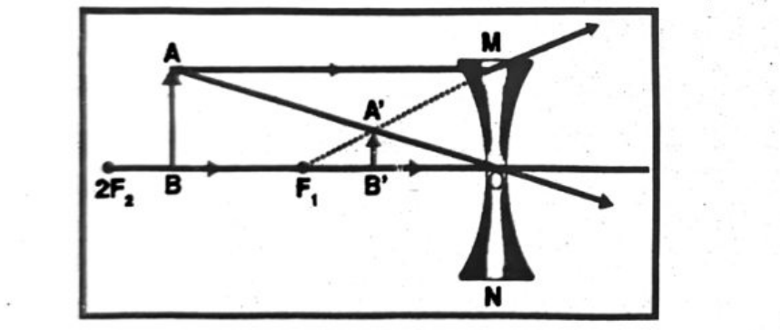
When an object is placed at infinity, a virtual image is formed at the focus. The size of the image is highly diminished and point size.
When an object is placed at a finite distance from the lens, a virtual image is formed between the optical centre and the focus of the convex lens. The size of the image is smaller than that of the object.
Image formation by Concave Lens
| Object location | Image location | Image nature | Image size |
|---|---|---|---|
| Infinity | At F1 | Virtual and Erect | Highly diminished, point-sized |
| Beyond Infinity and Optical Centre | Between Focus (F1) and Optical Centre (O) | Virtual and Erect | Diminished |
Difference between real and virtual images:
| Feature | Real Image | Virtual Image |
|---|---|---|
| Formation | Formed when light rays actually meet | Formed when light rays appear to meet |
| Image Location | Can be projected on a screen | Cannot be projected on a screen |
| Lens / Mirror Type | Formed by converging lenses or concave mirrors | Formed by diverging lenses or plane/convex mirrors |
| Orientation | Always inverted (upside down) | Always upright (right side up) |
| Example | Image on a cinema screen or camera sensor | Image seen in a mirror or magnifying glass |
OR (Second Answer)
Difference between real and virtual images:
Lenses can make two types of images one is called a real image and the other is called as virtual image.
| Real Image(s) | Virtual image(s) |
|---|---|
| can be caught on the screen | cannot be caught on the screen |
| is always inverted | is always erect |
| formed when the rays of light after reflection or refraction actually meet at some point | formed when the rays of light after reflection or refraction appear meet at some point |
| formed by the actual intersection of light rays | formed by the imaginary intersection of light rays |
| can be formed in a screen | can only be seen in mirrors |
| formed by only convex lens | concave lens, convex lens and plane mirrors also |
| formed on the other side of lens then the side of the object | formed on the same side of lens as the side of the object |
| Example is the image on our TV screen | Example is our reflection in mirror |
Applications of lenses:
Lenses, both convex and concave, have a wide range of applications in various fields. They are primarily used to manipulate light, forming images and correcting vision defects. Common applications include magnifying glasses, corrective eyewear, cameras, microscopes, and telescopes.
Specific Applications:
Magnifying Glasses:
Convex lenses are used to create magnified images of small objects, making them appear larger and closer.
Corrective Eyewear:
Eyeglasses and contact lenses utilize convex and concave lenses to correct vision problems like farsightedness (convex) and nearsightedness (concave).
Cameras:
Cameras employ lens systems to focus light onto a sensor or film, capturing images of scenes.
Microscopes:
Microscopes utilize multiple lenses (including convex lenses) to magnify tiny objects, allowing for detailed observation of microscopic structures.
Telescopes:
Telescopes use lens systems (sometimes with mirrors) to gather and focus light from distant objects like stars and planets, making them appear closer and brighter.
Lasers:
Concave lenses are used in some laser applications, such as those found in printers and medical equipment.
Medical Applications:
Lenses are used in various medical devices, including those for diagnosis and surgery, as well as for magnifying implants and examining structures.
Optical Instruments:
Lenses are essential components in many other optical instruments like binoculars, projectors, and optical measuring devices.
Magnifying glass:
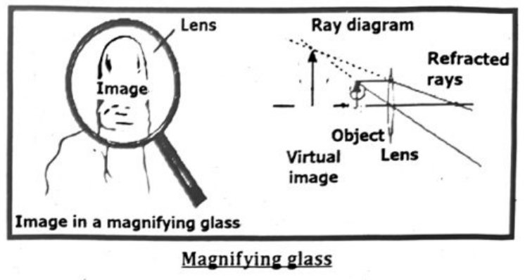
A single lens is used as magnifying glass which is a simple optical device designed to magnify objects. The lens used in the magnifying glass is convex lens. As we know that when an object is placed near the lens such that the object's distance from the lens is less than the distance of focal point of the lens, it produces an enlarged, erect and virtual image of the object. The eye perceives this image as being larger than the actual object.
To use a magnifying glass, we have to take care of the following steps:
Position: The position of object is crucial in the use of magnifying glass. Hold the magnifying glass close to the object you want to magnify.
Distance: Move the lens closer to or further from the object until the image comes into clear focus.
Viewing: Look through the lens to see the magnified image. The optical viewing distance is usually a few centimeters away from the object.
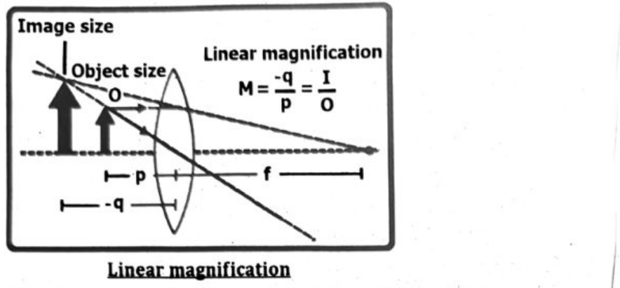
Linear magnification is the ratio of the height (or size) of the image to the height (or size) of the object. It tells us how much bigger or smaller the image is compared to the object.
Equation:
Magnification ($M$) = Height of image ($h_i$) / Height of object ($h_o$)
$M = h_i / h_o$
Example: An object 5 cm high is placed in front of a lens. The image formed is 10 cm high. Then the magnification is:
$M = h_i / h_o = 10 / 5 = 2$
| Condition | Explanation |
|---|---|
| $|M| > 1$ | The image size is less than that of object size. |
| $|M| < 1$ | The image size is greater than that of object size. |
| $|M| > 0$ | The image has the same vertical orientation as the object, called an upright image. |
| $|M| < 0$ | The image has the opposite vertical orientation as the object, called an inverted image. |
The ray diagram gives linear magnification as $M = -q/p = I/O$.
For a real image, we use the distance of image ‘+q’ as positive, and for a virtual image, we use the distance of image ‘−q’ as negative.
A single convex lens acts as a magnifying glass by converging light rays to create a magnified, virtual, and upright image of an object. When an object is placed closer to the lens than its focal length, the lens refracts the light, causing it to diverge as if coming from a point behind the lens, making the object appear larger.
Explanation:
Convex Lens:
A magnifying glass typically uses a convex lens, which is thicker in the middle than at the edges. This shape causes light rays to bend inward (converge).
Focal Point:
When parallel light rays pass through a convex lens, they converge at a specific point called the focal point.
Virtual Image:
When an object is placed closer to the lens than its focal point, the light rays diverging from the object are bent by the lens and appear to come from a larger, virtual image on the same side of the lens as the object.
Magnification:
This virtual image appears larger than the actual object, providing the magnifying effect. The closer the object is to the focal point, the greater the magnification.
Virtual and Upright:
The image formed by a magnifying glass is virtual (cannot be projected on a screen) and upright, meaning it’s not inverted.
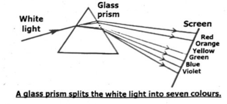
When white light passes through a prism, it is dispersed into its constituent colors due to refraction and the different wavelengths of light bending at different angles. This separation of light into a spectrum is called dispersion. Herschel’s experiment demonstrated that the spectrum extends beyond visible light, with infrared radiation detected by a thermometer placed just beyond the red end.
Explanation:
White Light and Wavelengths:
White light is a combination of all colors in the visible spectrum, each with a different wavelength.
Refraction:
When light passes from one medium to another (like air to glass), it changes speed and direction, a phenomenon called refraction.
Dispersion:
A prism’s refractive index varies slightly for different wavelengths of light. This means that each color bends at a slightly different angle as it passes through the prism. Violet light, having the shortest wavelength, bends the most, while red light, with the longest wavelength, bends the least.
Detection of Non-Visible Spectra:
Herschel’s experiment involved passing sunlight through a prism to create a spectrum. He placed a thermometer in the visible spectrum and noticed a temperature increase from violet to red. He then placed the thermometer just beyond the red end, in the area where no visible light appeared. The temperature reading there was even higher, indicating the presence of invisible radiation – infrared (IR) light.
Infrared Detection:
Herschel’s discovery showed that the electromagnetic spectrum extends beyond the visible range. By using a thermometer, he was able to detect the heat from the infrared radiation, proving it was a form of light that humans cannot see.
Prism Material:
The type of prism material also plays a role. For example, while standard glass prisms can disperse visible light and infrared, they may not transmit ultraviolet (UV) light, while quartz prisms can.
The traditional seven colors of the visible spectrum in order of increasing frequency (and decreasing wavelength) are: red, orange, yellow, green, blue, indigo, and violet. When ordered by decreasing frequency (and increasing wavelength), the colors are: violet, indigo, blue, green, yellow, orange, and red.
Here’s a more detailed breakdown:
Red: Has the longest wavelength and lowest frequency within the visible spectrum.
Orange: Shorter wavelength and higher frequency than red.
Yellow: Shorter wavelength and higher frequency than orange.
Green: Shorter wavelength and higher frequency than yellow.
Blue: Shorter wavelength and higher frequency than green.
Indigo: Shorter wavelength and higher frequency than blue.
Violet: Has the shortest wavelength and highest frequency within the visible spectrum.
The mnemonic “ROY G. BIV” is commonly used to remember the colors in order of increasing wavelength (decreasing frequency).
DISPERSION OF LIGHT BY PRISM:
Dispersion of light by a prism refers to the separation of white light into its constituent colors (red, orange, yellow, green, blue, indigo, and violet) as it passes through the prism. This occurs because different colors of light have different wavelengths, and a prism refracts (bends) light of different wavelengths at slightly different angles. Shorter wavelengths, like violet, are bent more than longer wavelengths, like red.
Explanation:
White light is a mixture of colors:
White light is not a single color, but rather a combination of all the colors of the visible spectrum.
Refraction at the prism’s surface:
When white light enters a glass prism, it slows down and bends (refracts) due to the change in medium. This initial refraction separates the colors slightly.
Different wavelengths, different refractions:
The key to dispersion is that the amount of bending (refraction) is different for each color. Violet light, with the shortest wavelength, bends the most,
Separation into a spectrum:
As the light continues through the prism and exits, the different colors are further separated. This results in a band of colors, known as a spectrum.
Formation of a rainbow:
The same principle of dispersion applies to the formation of rainbows in nature, where water droplets act as tiny prisms that separate sunlight into its colors.
Single lenses, both convex (converging) and concave (diverging), are fundamental components in a wide range of optical devices. Convex lenses are used for magnifying, correcting farsightedness, and focusing light, while concave lenses are used for correcting nearsightedness and spreading light. They are integral to devices like magnifying glasses, eyeglasses, cameras, telescopes, microscopes, and even lasers and flashlights.
Here’s a more detailed look at their applications:
Convex (Converging) Lenses:
Magnification: Convex lenses are the basis of magnifying glasses, allowing us to see smaller objects in more detail.
Vision Correction: They correct farsightedness (hyperopia), where the eye focuses light behind the retina, by converging light rays onto the retina.
Imaging: Cameras, telescopes, and microscopes utilize convex lenses to focus light and form images, whether it’s capturing a distant landscape, celestial objects, or microscopic details.
Lasers: In some laser applications, convex lenses can be used to focus the laser beam.
Concave (Diverging) Lenses:
Vision Correction: Concave lenses correct nearsightedness (myopia), where the eye focuses light in front of the retina, by diverging light rays before they reach the eye.
Spreading Light: They can be used in flashlights or other lighting devices to broaden the area of illumination.
Lasers: Concave lenses are used to spread out the laser beam in certain applications, preventing damage to equipment or focusing on larger areas.
Specialized Applications: They are also used in some scientific instruments and for specific optical setups.
Other Applications:
Eyeglasses: Both convex and concave lenses are used in eyeglasses to correct a range of vision problems.
Microscopes: Compound microscopes use a combination of lenses, including convex lenses, to achieve high magnification.
Telescopes: Telescopes also utilize convex lenses (or mirrors, in reflecting telescopes) to gather and focus light from distant objects.
Lasers: As mentioned, lenses play a role in controlling laser beams, both focusing and spreading them as needed.
Image formation in Camera:
In a camera, light from a scene enters through the lens and is focused onto a sensor (film or digital), creating an image. The lens bends (refracts) light rays, converging them to a point, and the sensor records the light intensity at each point, forming the image. The lens, aperture (controlling light), and focal length (distance to sensor) are key components in this process.
Here’s a more detailed breakdown:
Light Enters the Camera:
Light rays from the scene enter the camera through the aperture, which is an opening that can be adjusted to control the amount of light entering the camera.
Light is Refracted by the Lens:
The lens, typically a convex lens, bends the incoming light rays. This bending is called refraction, and it’s the lens’s ability to focus light from a large area onto a smaller area on the sensor.
Image Formation on the Sensor:
The focused light rays then reach the camera’s sensor (either film or a digital sensor like CCD or CMOS). The sensor converts the light into electrical signals or chemical changes, creating an image.
Key Components:
Lens: The lens is responsible for focusing the light. The shape and curvature of the lens determine how it refracts light.
Aperture: The aperture is an adjustable opening within the lens that controls the amount of light entering the camera. A wider aperture (smaller f-number) lets in more light and can create a shallow depth of field (blurry background).
Focal Length: The focal length is the distance between the lens and the sensor when the image is in focus. Different focal lengths provide different fields of view and magnification.
Image Characteristics:
Depth of Field: The depth of field is the range of distances in the scene that appear acceptably sharp in the image. It is influenced by the aperture and focal length.
Focus: The lens focuses light from different distances onto the sensor. Proper focus ensures that the image is sharp and clear.
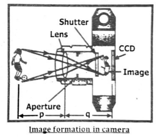
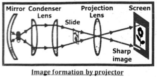
Image Formation in Projector:
Projectors create an image by manipulating light to project a magnified and focused image onto a screen. This is achieved through a combination of a light source, lenses, and a spatial light modulator, which selectively blocks or allows light to pass through. The modulated light is then projected onto a screen, forming the visible image.
Here's a more detailed explanation:
Light Source:
Projectors use a powerful light source, either a lamp or an LED, to generate a bright beam of light.
Spatial Light Modulator:
This is the key component that determines which parts of the light beam are allowed to pass through and which are blocked. Common technologies include:
Liquid Crystal Displays (LCD): These use liquid crystals to control the polarization of light, effectively acting as tiny shutters to create the image.
Digital Micro mirror Devices (DMD): These use tiny mirrors that can be individually tilted to reflect light towards or away from the lens.
Laser Scanning: Some newer projectors use lasers to scan across the screen, creating the image directly.
Lenses:
The light modulated by the spatial light modulator is then passed through a series of lenses. These lenses serve several purposes:
Magnification: They enlarge the image to the desired size.
Focusing: They ensure the image is sharp and focused on the screen.
Inversion: In some cases, lenses may be used to invert the image, which is then corrected by inverting the original image source (like a slide).
Projection:
The focused and magnified light is then projected onto a screen or wall, creating a visible image.
In essence, the projector takes a digital image, converts it into a light pattern, and then uses lenses to project a magnified and focused version of that pattern onto a surface.
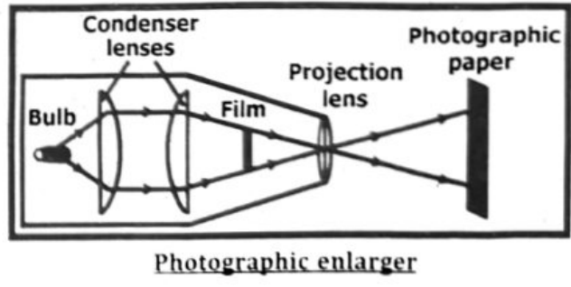
Photographic Enlarger:
A photographic enlarger projects a magnified image of a negative onto photographic paper allowing for the creation of prints larger than the original negative. The process involves several key steps: preparing the enlarger, focusing the image, adjusting exposure, and developing the print.
Here's a more detailed breakdown:
Preparation:
Negative Placement: The negative is carefully placed into the enlarger's negative carrier, ensuring it's clean and free of dust.
Enlarger Setup: The enlarger is positioned above an easel holding the photographic paper, and the height is adjusted to achieve the desired print size.
Red safelight: The darkroom is illuminated with a red safelight, as photographic paper is sensitive to white light.
Focusing:
Initial Focusing: The enlarger’s lens is opened to its widest aperture, and the image is projected onto the paper. A focus scope or grain focuser can be used to achieve a sharp focus on the film grain.
Refining Focus: The lens aperture is then stopped down (closed) to a smaller f-stop (e.g., f/8) to increase sharpness and depth of field.
Exposure:
Test Strips: Before making a full print, a test strip of photographic paper is exposed to the projected image for varying durations. This helps determine the optimal exposure time.
Full Print Exposure: Once the correct exposure time is found, the full sheet of photographic paper is exposed using the enlarger.
Developing:
Developing: The exposed paper is submerged in a developer solution for a specific time, where the image becomes visible.
Stop Bath: The paper is then transferred to a stop bath to halt the development process.
Fixing: Next, the paper is placed in a fixer solution to stabilize the image and make it insensitive to light.
Washing: Finally, the print is thoroughly washed in running water to remove any remaining chemicals.
Drying and Finishing:
Drying: The print is carefully dried, and it’s ready for viewing or further processing, such as mounting or retouching.
VISIBLE SPECTRUM:
The visible spectrum is the portion of the electromagnetic spectrum that is visible to the human eye, encompassing the colors of the rainbow: red, orange, yellow, green, blue, indigo, and violet. Each color corresponds to a specific range of wavelengths and frequencies of light, with red having the longest wavelength and violet the shortest.
In order of frequency and wavelength the seven colors can be given as:
Red:
Light of red color has the largest range of wavelengths i.e. ranging from 620 – 750 nm which are among the largest wavelengths in visible spectrum. Conversely this range has the lowest frequencies ranging from 400 – 480 Thz.
Orange:
Light of orange color has larger wavelengths than the red color and smaller than rest of the colors. The wavelength range for orange color is 590 – 620 nm with frequencies from 480 – 510 Thz.
Yellow:
Light of yellow color has larger wavelengths than the red and orange colors and smaller than rest of the colors. The wavelength range for yellow color is 565 – 590 nm with frequencies from 510 – 530 Thz.
Green:
Light of green color has intermediate wavelength range within visible spectrum. The wavelength range for green color is 500 – 565 nm with frequencies from 530 – 600 Thz.
Blue:
Light of blue color has larger wavelengths than the indigo and violet colors and smaller than rest of the colors. The wavelength range for blue color is 485 – 500 nm with frequencies from 600 – 620 THz.
Indigo:
Light of indigo color has larger wavelengths than the violet color and smaller than rest of the colors. The wavelength range for indigo color is 450 – 485 nm with frequencies from 620 – 670 THz.
Violet:
Light of violet color has the smallest wavelengths in the entire range of the visible spectrum and highest frequencies among all the colors in visible light. The wavelength range for violet color is 400 – 450 nm with frequencies from 670 – 790 THz.
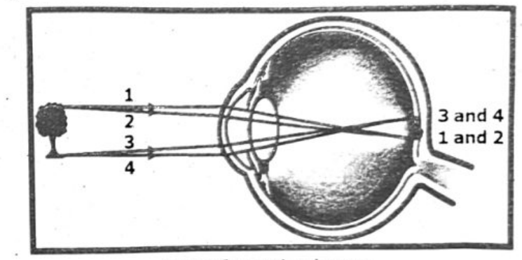
FORMATION OF IMAGE ON NORMAL EYE:
The image for a normal eye is made on retina i.e. all the rays coming from the object focused on retina which makes the clear image of the object on eye.
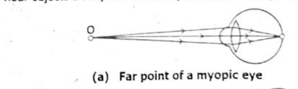
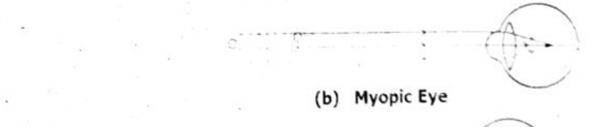
SHORT-SIGHTEDNESS:
The short-sightedness or myopia is the condition in which a person can see near objects clearly but distant objects appear blurry.
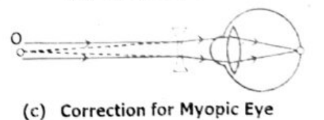
Correction of Near Sightedness / Short Sightedness
Correction: The shortsightedness can be corrected by using a concave or a diverging lens.
The diverging lens causes the rays to diverge before they reach the eye, so the image is formed on the retina and not in front of it
LONG-SIGHTEDNESS:
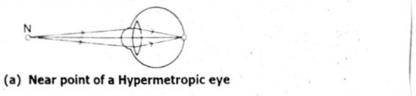
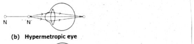
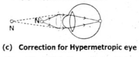
The longsightedness or hyperopia is the condition in which a person can see distant objects clearly but near objects appear blurry to him. Hyperopia is also called as hypermetropia.
Correction: The long-sightedness can be corrected by using a convex or converging lens.
The converging lens causes the rays to converge before they reach the eye, so the image is formed on the retina and not behind it
Correction of Far Sightedness / Long Sightedness
STRUCTURE OF HUMAN EYE:
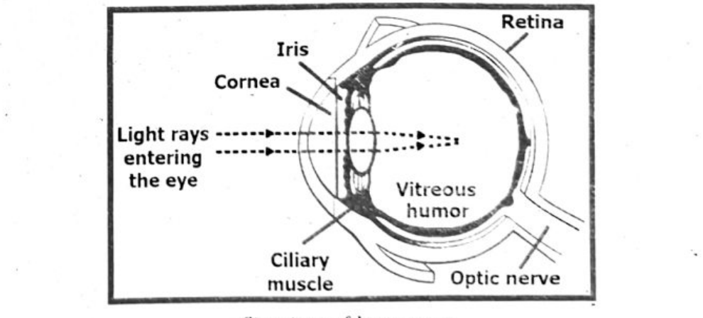
The human eye is a complex, spherical structure composed of three main layers: the fibrous, vascular, and nervous layers. These layers enclose the aqueous humor, lens, and vitreous body, all of which play a role in vision. The outer layer, the fibrous layer, includes the cornea and sclera, providing shape and protection. The middle vascular layer contains the choroid, ciliary body, and iris, responsible for blood supply and regulating light. Finally, the inner nervous layer, the retina, contains light-sensitive cells that convert light into electrical signals, which are then transmitted to the brain via the optic nerve.
Here’s a more detailed breakdown:
Fibrous Layer:
Cornea: The transparent, curved, front part of the eye that refracts light entering the eye.
Sclera: The white outer layer that protects the eyeball and provides attachment for the muscles that control eye movement.
Vascular Layer:
Choroid: A layer rich in blood vessels that provides nourishment to the eye and absorbs excess light.
Ciliary body: Contains the ciliary muscle, which controls the shape of the lens for focusing, and produces aqueous humor.
Iris: The colored part of the eye that controls the size of the pupil.
Pupil: The opening in the iris that allows light to enter the eye.
Nervous Layer:
Retina: The light-sensitive layer at the back of the eye containing photoreceptor cells (rods and cones) that convert light into electrical signals.
Optic nerve: Transmits the electrical signals from the retina to the brain.
Other Important Structures:
Aqueous humor: Fluid filling the space between the cornea and lens, maintaining eye pressure and shape.
Lens: A transparent, flexible structure behind the pupil that focuses light onto the retina.
Vitreous humor: A gel-like substance filling the space between the lens and retina, helping the eye maintain its shape.
Ciliary muscles: Muscles that control the shape of the lens.
Fovea: A small depression in the retina responsible for sharp central vision.
Converging and diverging lenses are used to correct long-sightedness and short-sightedness, respectively. Converging (convex) lenses are used to correct long-sightedness (hyperopia), where distant objects appear blurry because the light focuses behind the retina. These lenses help to converge the light rays, bringing the focal point forward onto the retina. Conversely, diverging (concave) lenses correct short-sightedness (myopia), where near objects appear blurry because the light focuses in front of the retina. These lenses diverge the light rays, pushing the focal point back onto the retina.
Long-sightedness (Hyperopia):
Problem: The eyeball is too short, or the cornea and lens don’t focus light properly, causing light rays to converge behind the retina.
Solution: Converging (convex) lenses are used to increase the convergence of light rays, bringing the focal point forward onto the retina.
Short-sightedness (Myopia):
Problem: The eyeball is too long, or the cornea and lens focus light in front of the retina.
Solution: Diverging (concave) lenses are used to diverge light rays, pushing the focal point back onto the retina.
FORMATION OF IMAGE ON NORMAL EYE:
The image for a normal eye is made on retina i. e. all the rays coming from the object focused on retina which makes the clear image of the object on eye. The ray diagram for the formation of image by eye on retina is shown in figure.
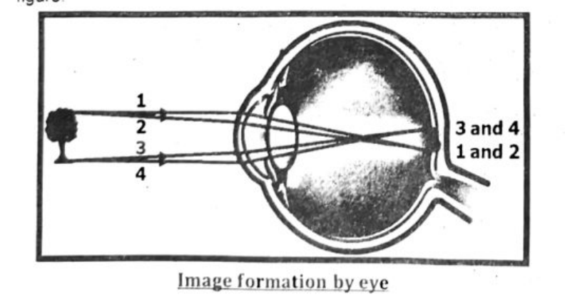
The light rays from the object after converging from the lens of eye focused on retina. Consider the path of two light rays coming from the top of the object named ‘1’ and ‘2’ again coincide on retina similarly the rays coming from the bottom of the object also coincide at retina to make a clear image on retina.
COLOR PERCEPTION:
The human eye, and the eyes of many other organisms, process color using a combination of rods and cones in the retina and the brain's visual cortex.
Humans have three types of cone cells, each sensitive to different wavelengths of light (red, green, and blue), which allow us to perceive a wide spectrum of colors through combinations of these signals.
In contrast, some animals like the mantis shrimp have a more complex visual system with up to 12 different types of photoreceptors, enabling them to see a broader range of colors and even perceive ultraviolet light.
a. Rods, Cones, and the Brain in Human Color Vision:
Rods: These photoreceptors are highly sensitive to light and are crucial for vision in low-light conditions, but they do not contribute to color perception.
Cones: These cells are responsible for color vision in brighter light. Humans have three types of cones, each containing a different photopigment (visual pigment) that is most sensitive to a particular range of wavelengths: short (blue), medium (green), and long (red).
Brain: The signals from the cones are transmitted to the brain via the optic nerve. The brain then interprets the combinations of signals from the three cone types to create the perception of a wide range of colors.
b. Examples of Varying Color Perception:
Humans: As described above, humans have trichromatic color vision, using three types of cones to perceive color.
Birds, Insects, and Fish: Many of these animals have tetrachromatic vision, meaning they possess four types of cones, allowing them to perceive ultraviolet light in addition to the colors visible to humans.
Mantis Shrimp: Mantis shrimp possess exceptionally complex eyes with unique capabilities, including the ability to perceive a wide range of colors (including UV and polarized light), and depth perception using a single eye. This crustacean has a highly sophisticated visual system with up to 12 types of photoreceptors, enabling them to see a wider range of colors than humans and also perceive polarized light.
Dogs: Dogs have dichromatic vision, meaning they have only two types of cones (blue and yellow). They cannot distinguish between red and green, and their overall color perception is less rich than that of humans.
Yes, it's accurate to say that extreme gravity, like that produced by black holes, can bend light in a way that acts like a lens, a phenomenon known as gravitational lensing. This bending occurs because massive objects warp the fabric of spacetime, and light follows the curves of this warped space.
Explanation:
Gravitational Lensing: General relativity predicts that massive objects distort space-time, and light, when passing near these objects, will have its path bent.
Analogy to a Lens: This bending can create multiple images, arcs, or even rings of light from a distant object, resembling the way a lens focuses or distorts light.
Black Holes and Lensing: Black holes, with their immense gravity, are particularly effective at gravitational lensing. They can bend light around them, even to the point where light can orbit the black hole before reaching an observer.
Observational Evidence: Astronomers use gravitational lensing to study distant galaxies and black holes, even those we can't directly observe. The bending and magnification of light provides clues about the properties of the lensing object.
Extreme Lensing: In some cases, light can be bent so severely by a black hole that it can orbit the black hole multiple times before reaching us, resulting in highly distorted and amplified images.
GRAVITATIONAL LENSING:
The phenomenon in which a massive celestial body causes a sufficient curvature of space-time for the path of light around it to be visibly bent as if by a lens is called gravitational lensing.
Gravitational lensing is a phenomenon predicted by Einstein's theory of general relativity where the gravity of a massive object bends and magnifies the light from a distant object behind it, acting like a lens. This effect allows astronomers to observe objects that would otherwise be too faint or distant to see directly.
Explanation:
Spacetime Distortion:
Einstein's theory describes gravity not as a force, but as a curvature of spacetime caused by mass and energy.
Massive objects like galaxies or galaxy clusters warp the fabric of spacetime around them.
Light Bending:
Light, which normally travels in straight lines, follows the curves in spacetime.
When light from a distant source passes near a massive object, its path is bent, or deflected, by the curvature of space-time.
Magnification and Distortion:
This bending of light can cause the distant object to appear magnified, distorted, or even appear as multiple images.
The massive object acts like a lens, focusing and redirecting the light from the background object.
Strong lensing produces multiple images, arcs, or rings, while weak lensing causes subtle distortions in the shape of background galaxies.
Applications:
Observing Faint Objects: Gravitational lensing allows astronomers to see objects that would be too distant or faint to observe directly, potentially revealing the early universe or distant galaxies.
Studying Dark Matter: The way light bends around galaxies can be used to map the distribution of dark matter, a mysterious substance that makes up a large portion of the universe's mass.
Testing General Relativity: Gravitational lensing provides a way to test Einstein's theory of general relativity in extreme gravitational environments.
Similarly in some cases when the source lies exactly behind a galactic object due to bending of light all around the intervening object makes a ring of light around it and is called “Einstein rings”.
Acoustic lenses are specially shaped objects made from certain materials that can focus or spread out sound waves, similar to how optical lenses affect light. They are used to direct sound for clearer hearing, medical imaging or underwater detection. Acoustic lenses are designed with specific materials and shapes to manipulate sound waves, causing them to either converge (focus) or diverge (spread out). They utilize the refractive properties of sound in different mediums, much like optical lenses, to control the direction and intensity of sound waves.
Explanation:
Focusing: Acoustic lenses can concentrate sound energy into a smaller area, increasing its intensity. This is achieved by shaping the lens to refract the sound waves so they converge at a focal point.
Diverging: Conversely, acoustic lenses can also be designed to spread out sound waves, reducing their intensity in a specific area.
Materials and Shape: The material composition and the curvature of the lens are crucial in determining its focusing or diverging properties. For example, a convex lens with specific curvature can focus sound waves.
Applications: Acoustic lenses are used in various applications, including medical imaging (ultrasound), underwater acoustics, and noise control.
The aim of the acoustic lens is to focus sound in much the same way that an optical lens focuses light. In loudspeakers a mechanical device used to improve the dispersion of high frequencies so that dispersion is much more
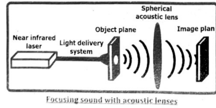
TYPES OF ACOUSTIC LENSES:
There are two commonly used types of acoustic lenses i. e. the slant-plate lenses and perforated-plate lenses.
(i) Slant-Plate Lens:
The design of the most commonly seen acoustic lens is the slant-plate lens which utilizes a series of plates with carefully calculated hyperbolic shapes which results in a horizontal response patterns. They make to select portion of expanding pressure wave to travel farther than other portions of the wave this tend to shape the pressure wave by controlling the dispersion.
(ii) Perforated-Plate lens:
Perforated-plate lenses consist of a collection of perforated barriers at the horn mouth. These perforated screens are actually ring shaped with varying sizes of center cutouts. These perforated plate lenses can diverge as well as converge the sound just like diverging and converging lenses do with the light signals.
MATERIAL AND SHAPES OF ACOUSTIC LENSES:
Acoustic lenses can be made from various materials like plastic, epoxy, rubber and liquids due to reasons given below:
(a) Plastic: Plastic materials are commonly used for making acoustic lenses because it can easily be fabricated and have good acoustic properties.
(b) Epoxy: Epoxy is also commonly used material for making acoustic lenses it offer good sound permeability and can be molded into specific shapes.
(c) Rubber: Rubber is used in acoustic lenses for their flexibility and the ability to deform the lenses.
(d) Liquid: Some acoustic lenses use liquid filled chambers to converge or diverge sound waves.
Similarly acoustic lenses come in different shapes each shape serves specific purpose. They can be shaped in spherical, ellipsoidal, parabolic and gradual geometric curves as explained here.
(e) Spherical Acoustic Lenses: These acoustic lenses have curved surface like a sphere, they focus or diverge the sound waves according to their curvature.
(f) Ellipsoidal Acoustic Lenses: These are similar to spheres but a little elongated in one direction (somehow like an egg) they can focus sound waves in a specific direction.
(g) Parabolic Acoustic Lenses: These acoustic lenses have a parabolic shape and are excellent at focusing sound waves to a single point.
(h) Gradual Geometric Acoustic Lenses: Lenses with gradual geometric curves achieve gradient refractive index distribution allowing precise acoustic focusing.
Applications of acoustic lenses:
Acoustic lenses are important for applications like under water imaging, sonar systems and medical ultrasound etc. They are also used in non-destructive testing of materials which are opaque to light but sound waves can penetrate the material and find the voids and cracks without destructing the material. Now researchers are exploring 3-D printed meta-materials with balcony like structures to create impact resistant acoustic lenses.
Examples:
- GIVEN:
Incident ray ‘A’ is parallel to reflected ray ‘B’ - REQUIRED:
Angle ‘α’ = ? - SOLUTION:
To find the value of angle we use laws of reflection as for the incident ray at ‘A’ and the reflected incident ray at ‘B’ to be parallel. and the angles (i + r) and (i’ + r’) have to be supplementary:
$i + r + i' + r' = 180^\circ$
By laws of reflection. $i = r$ and $i' = r'$
Using these values we get:
$i + i + i' + i' = 180^\circ$ and $i + i' = 90^\circ$
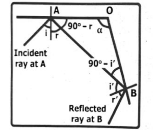
In the triangle ‘AOB’ we have:
$\alpha + (90^\circ - r) + (90^\circ - i') = 180^\circ$, or $\alpha = r + i' = i + i'$.
Therefore, $\alpha = 90^\circ$. [ANSWER]
So, for incident ray ‘A’ and reflected ray ‘B’ to be parallel, ‘α’ must be 90°.
- GIVEN:
Refractive index ‘n’ = 2.419
Speed of light ‘c’ = $3 \times 10^8$ m s−1 - REQUIRED:
Speed of light in medium ‘v’ = ? - SOLUTION:
To find the speed of light in diamond we use formula: $n = \frac{c}{v}$.
Rearranging: $v = \frac{c}{n}$.
Putting values: $v = \frac{3 \times 10^8\ \text{m s}^{-1}}{2.419}$.
Therefore, $v = 1.24 \times 10^8$ m s−1. [ANSWER]
The speed of light reduces to $1.2 \times 10^8$ m s−1.
- GIVEN:
Refractive index of air ‘n1’ = 1
Angle of incident light ‘θi’ = 37°
Angle of refracted light ‘θr’ = 21° - REQUIRED:
Refractive index of medium ‘n2’ = ? - SOLUTION:
The Snell's law can be written as: $\frac{n_2}{n_1} = \frac{\sin\theta_i}{\sin\theta_r}$.
Putting values: $\frac{n_2}{1} = \frac{\sin 37^\circ}{\sin 21^\circ}$.
Therefore, $n_2 = 1.68$. [ANSWER]
This is the refractive index of a type of glass which is used for the core of optical fibers.
- GIVEN:
The refractive index of polystyrene ‘n’ = 1.49 - REQUIRED:
Critical angle ‘θc’ = ? - SOLUTION:
To find the critical angle we can use formula: $\sin\theta_c = \frac{1}{n}$.
Putting values: $\sin\theta_c = \frac{1}{1.49}$ or $\theta_c = \sin^{-1}(0.671)$.
Therefore, $\theta_c = 42.2^\circ$. [ANSWER]
This mean that the light ray moving in the polystyrene if strikes the boundary with an angle greater than 42.2° will be totally reflected internally.
GIVEN:
- Height of object ‘O’ = 2 cm
- Distance of object ‘p’ = 6 cm
- Magnification ‘M’ = 3
REQUIRED:
- Height of image ‘I’ = ?
- Distance of image ‘q’ = ?
- Nature of image = ?
SOLUTION:
The relation for magnification is: $M=\frac{I}{O}$ or $I=MO$.
Using values, $I=(3)(2\text{ cm})$. Therefore, $I=6\text{ cm}$. [ANSWER]
To find the distance of image we can again use magnification relation as: $\frac{I}{O}=\frac{q}{p}$ or $q=p\times\frac{I}{O}$.
Using values, $q=(6\text{ cm})\times\frac{6\text{ cm}}{2\text{ cm}}$. Therefore, $q=18\text{ cm}$. [ANSWER]
As the object is placed outside of the focal point hence the image formed in this case will be real, inverted, enlarged and opposite side of the lens as that of object.
Summary
- Optics is the science of light and its interaction with matter.
- Reflection of light is when a ray of light approaches a smooth polished surface and bounces back is called reflection.
- First law of reflection states that the incident ray, the reflected ray and the normal all lie in same plane.
- Second law of reflection states that the angle of incident ray is equal to the angle of the reflected ray.
- Refraction of light is the phenomenon in which the light ray's direction changes when it enters from one medium to another.
- Speed of light in vacuum is constant but in other transparent media the speed of light decreases, its speed depends upon the density of the medium.
- Refractive index is the measure of bending of a light ray when passing from one medium to another.
- Perspex Block is a tough transparent plastic block which is used instead of glass blocks.
- Total internal reflection is the phenomenon in which a light ray travelling in denser medium bounces back to the same medium after striking the boundary of a rarer medium.
- Critical Angle is the angle of incident light ray for which in spite of transmission into other medium the light ray moves along the boundary between the two media.
- Optical Fibers are the doubly refractive indices concentric tubes of glass or plastic which are used for transmission of light using the phenomenon of total internal reflection.
- Lenses are transparent objects that refract light in a specific way to form images.
- Convex Lens is a type of lens which is thick from the center and thin from the outer edges; it converges the parallel light rays to a single point.
- Concave Lens is a type of lens which is thin from the center and thick from the outer edges; it diverges the parallel light rays.
- Focal length is the distance from the lens to its focal point; for a converging lens the focal length is positive while for a diverging lens the focal length is negative.
- Magnifying glass is a single lens device which is used to see bigger images of the objects.
- Dispersion from a prism is the phenomenon in which white light splits into its seven constituent colors due to different extent of refraction.
- Near Point is the minimum distance at which if the object is placed we have clear image on our retina.
- Gravitational Lensing is the phenomenon in which light bends, while passing by a heavy galactic object due to its strong gravity.
- Acoustic Lensing is the technique in which some materials are used to focus or diverge sound waves.