
Constructed Response Questions:
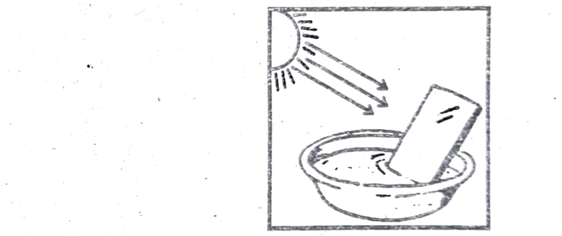
(a) Why the seven color pattern is shown on the wall?
(b) What is the role of water in this phenomenon?
(c) Discuss the basic principle used here which converts the white sunlight into seven colors?
Ans: The seven-color pattern, resembling a rainbow, appears on the wall due to the dispersion of white light into its constituent colors as it passes through the water and reflects off the mirror. The water acts as a prism, refracting and separating the different wavelengths of light, while the mirror reflects the light onto the wall.
(a) Why the seven-color pattern is shown on the wall?
White light is actually a combination of all colors of the visible spectrum. When this light enters water, it slows down and bends, a phenomenon called refraction. Different colors of light bend at slightly different angles. This separation of colors is called dispersion. When the light then reflects off the mirror and back into the air, the colors are further separated and projected onto the wall, creating the colorful pattern.
(b) What is the role of water in this phenomenon?
Water acts as a medium that causes light to bend (refract) and enhances the separation of colors. It is the key element in this experiment that allows for the dispersion of light. The water’s refractive index (how much it bends light) is different from air, causing the light to change direction and separate into its component colors when it enters and exits the water.
(c) Discuss the basic principle used here which converts the white sunlight into seven colors?
The basic principle is refraction and dispersion of light. When light passes from one medium to another (in this case, from air to water and then back to air), it changes speed and direction. This change in direction is refraction. If the light is white light, the different colors within it will bend at slightly different angles due to their different wavelengths. This separation of colors is called dispersion. The combination of refraction and dispersion results in the separation of white light into its constituent colors, creating the colorful pattern seen on the wall.
Short Questions:
Ans: The index of refraction is always greater than or equal to one because it represents the ratio of the speed of light in a vacuum to its speed in a given medium and light travels at its maximum speed in a vacuum. Since no material medium can make light travel faster than it does in a vacuum, the ratio will always be greater than or equal to one.
- If $v < c$, then $n = \frac{c}{v} > 1$.
- If $v = c$ (which occurs only in a vacuum), then $n = \frac{c}{c} = 1$.
Any medium will have an index of refraction greater than 1 because light travels slower in that medium than in a vacuum.
Ans: The primary physical process responsible for the decrease in the speed of light within material mediums is refraction, specifically the interaction between light waves and the atoms within the medium. Light slows down because it is absorbed and re-emitted by the atoms, effectively creating a wave that propagates at a reduced speed.
OR (Second Answer)
The physical process responsible for the decrease in the speed of light in material mediums is the interaction of light with the atoms and molecules of the medium. As light enters the material, its electromagnetic waves cause the charged particles (mainly electrons) to oscillate. These oscillating charges then emit their own electromagnetic waves, which interfere with the original wave. This repeated absorption and re-emission process slows down the net propagation of light through the medium, effectively reducing its speed compared to its speed in a vacuum.
Ans: Powder removes shine from a nose by creating a rough surface that scatters light, a process called diffuse reflection, instead of reflecting it in a single direction. This scattering reduces the intensity of reflected light reaching the eyes, making the nose appear less shiny. Additionally, powder absorbs excess oil, which is a major contributor to shine. In summary, powder eliminates shine by transforming a smooth, specularly reflecting surface into a rough surface that scatters light in many directions, thus reducing the coherent reflection that causes shine.
Ans: An object submerged in water appears to be closer to the surface than it actually is due to the refraction of light. When light travels from water into air, it bends or refracts, causing our eyes to perceive the object's location at a shallower depth. This perceived shallower depth is known as the “apparent depth,” while the object's actual depth is the “real depth.”
Example:
A coin at the bottom of a glass of water appears raised because the light rays from the coin refract as they exit the water, causing them to diverge and making the coin appear closer to the surface.
Ans: The refractive index of air decreases as temperature increases because warmer air is less dense. When air is heated, its molecules move faster and farther apart, reducing the density of the air. Since the refractive index is inversely proportional to density, a decrease in density leads to a decrease in the refractive index.
Example:
Hot air, being less dense, will allow light to travel through it slightly faster than cooler air. This difference in speed leads to a lower refractive index for the hotter air.
In summary, as the temperature of air increases, its density decreases, resulting in a lower refractive index because there are fewer air molecules per unit volume to interact with the light.
Ans: Rainbows, including double and triple rainbows, are formed by the dispersion of light through water droplets. A single rainbow (primary rainbow) results from one internal reflection of sunlight within a raindrop, while a double rainbow forms when light undergoes two internal reflections. A triple rainbow requires a third internal reflection within the raindrop. Triple rainbows are possible with three internal reflections, but they are much fainter and rarer than double rainbows.
Ans: Yes, a virtual image can be photographed. While a virtual image cannot be projected onto a screen, the light rays that appear to emanate from it can be captured by a camera lens, allowing for a photograph of the virtual image.
Example:
When you take a picture of yourself in a mirror, you are photographing a virtual image. The camera lens focuses the diverging light rays from the virtual image behind the mirror onto the camera’s sensor, capturing the image.
Ans: In optics, negative magnification indicates that the image formed is inverted relative to the object. This means the image appears upside down compared to the original object. It’s a characteristic of real images, which are formed when light rays converge, such as with a concave mirror when the object is placed beyond the center of curvature or with a convex lens when the object is placed outside the focal point.
Examples:
- A concave mirror used as a shaving mirror (object placed close to the mirror, within the focal length) produces a magnified, upright, virtual image (positive magnification).
- A concave mirror used to focus sunlight (object placed far from the mirror, beyond the center of curvature) produces an inverted, real image (negative magnification).
- A convex lens used as a magnifying glass (object placed within the focal length) produces a magnified, upright, virtual image (positive magnification).
- A convex lens used to focus light from a distant object produces an inverted, real image (negative magnification).
Ans: Yes, a flat, transparent piece of glass can be considered a lens with infinite focal length. In this case, it does not form a real image in the way a curved lens does. Instead, it can be thought of as delaying the divergence of light rays, making an object appear slightly closer than it actually is. In summary, a flat transparent glass slab can be regarded as a lens with an infinite focal length because it doesn’t converge or diverge light. It forms a virtual image that appears at the same distance as the object, though slightly displaced.
Ans: When a lens is dipped in water, its focal length increases. This is because the refractive index of water is less than the refractive index of air, causing light to bend less when passing from water into the lens compared to when passing from air into the lens. This reduced bending results in a longer focal length, meaning the lens will focus light at a greater distance. In summary, when a lens is dipped in water, its focal length increases because the difference in refractive indices between the lens material and the surrounding medium decreases, reducing the lens’s ability to bend light.
Ans: When you open your eyes in water, the refractive index difference between water and the cornea is much smaller than between air and the cornea. This causes insufficient bending of light rays, leading to improper focusing on the retina and resulting in a blurry image.
Ans: The statement that a real image is always inverted is generally true for simple optical systems, but it’s not universally true. While real images formed by converging lenses (like those in cameras or projectors) and concave mirrors (under certain conditions) are indeed inverted, other optical systems can produce real, erect images.
Example:
For example, in a concave mirror or a converging lens, when the object is placed beyond the focal point, the resulting image is inverted. However, there are exceptions, such as when the object is placed very far away (at infinity) from a concave mirror, where the image can appear upright and small. So, while real images are typically inverted, the exact orientation depends on the object’s position relative to the lens or mirror.
Ans: Gravitational lensing is not strictly optical in the way we usually think of lenses like those made of glass. While it shares some visual similarities, the mechanism is fundamentally different.
- Optical lenses use refraction through a material’s refractive index to bend light, whereas gravitational lensing relies on the curvature of space-time caused by mass and gravity, which redirects light’s path.
- In essence, gravitational lensing is a consequence of Einstein’s theory of general relativity, where gravity is not just a force, but a curvature of space-time. This curvature affects the path of light, causing it to bend and distort, similar to how a lens bends light, but without the need for a physical lens.
Ans: Curved ceilings in school halls, especially those used for assemblies or performances, are designed to enhance sound quality. The curvature helps to distribute sound waves more evenly throughout the space, preventing dead spots and ensuring that everyone can hear clearly. Additionally, curved ceilings can improve visibility and add to the aesthetic appeal of the hall.
- The curved ceilings of school halls are designed to diffuse sound waves, promoting a more even distribution of sound and improving the overall acoustic quality of the space.
- In essence, the curved ceiling acts as a large, natural soundboard, optimizing the acoustics and visual experience within the hall.
Ans: An empty container produces a louder sound than a filled one because the internal space allows for greater and more efficient vibration of air molecules, leading to a larger amplitude of sound waves. When a container is filled, the liquid or solid material dampens the vibrations, reducing the amplitude and thus the sound produced.
- The amplitude of a sound wave determines its loudness. A larger amplitude means a louder sound. The vibrations in an empty container have a larger amplitude compared to a filled one, resulting in a louder sound. Empty containers can also act as resonators, amplifying ambient sounds and making them more noticeable.
- In summary, an empty container produces more sound because it can vibrate more freely at its resonant frequency, while a filled container experiences damping and energy transfer, which reduces the amplitude of its vibrations and the loudness of the sound produced.
Long Questions:
QIV. Give a detailed response to the following questions.
Reflection of Light:
Reflection of light is the phenomenon where light rays bounce back after hitting a surface. The laws of reflection dictate how this bouncing occurs.
Laws of Reflection:
- The first law states that the angle of incidence (the angle at which light hits the surface) is equal to the angle of reflection (the angle at which light bounces off the surface).
- The second law states that the incident ray, the reflected ray, and the normal (a line perpendicular to the surface at the point of incidence) all lie in the same plane.
Explanation of the Laws of Reflection:
Angle of Incidence = Angle of Reflection
Imagine a ray of light hitting a mirror. The angle between the incoming ray and a line perpendicular to the mirror (the normal) is the angle of incidence. The angle between the outgoing ray and the same normal is the angle of reflection. These two angles are always equal.
The first law states that $\theta_i = \theta_r$.
Coplanar:
The incident ray, the reflected ray, and the normal to the surface at the point where the light strikes the surface all exist on the same plane. Think of it like a flat sheet of paper; all three lines would lie on that piece of paper.
Types of Reflection:
There are two main types of light reflection: specular reflection and diffuse reflection. Specular reflection occurs when light bounces off a smooth surface, like a mirror, in a single, predictable direction. Diffuse reflection, on the other hand, happens when light hits a rough surface and scatters in many directions.
Specular Reflection:
- Also known as regular reflection.
- Occurs when light strikes a smooth, reflective surface, like a mirror or still water.
- The angle of incidence (the angle at which light hits the surface) is equal to the angle of reflection (the angle at which light bounces off).
- The reflected light rays travel in the same direction, creating a clear, focused image.
Diffuse Reflection:
- Occurs when light strikes a rough, uneven surface like a piece of paper or a wall.
- The light rays bounce off the surface at many different angles, scattering the light.
- This scattering effect is why we can see objects from different angles, even if they are not perfectly smooth.
- It is the primary way we see most objects in our everyday environment.
Image Formation in Plane Mirrors:
Images in plane mirrors are formed through reflection where light rays from an object bounce off the mirror’s surface and appear to originate from a point behind the mirror. This creates a virtual image that is the same size and distance behind the mirror as the object is in front of it.
Explanation:
(i) Light Reflection:
When light rays from an object strike a plane mirror, they are reflected according to the law of reflection, which states that the angle of incidence (the angle at which light hits the mirror) is equal to the angle of reflection (the angle at which light bounces off).
(ii) Virtual Image Formation:
The reflected light rays appear to diverge from a point behind the mirror, creating a virtual image. This image is not a physical location where light rays converge; instead, it is the point where the reflected rays, if extended backward, would intersect.
(iii) Image Characteristics:
- Virtual: The image is not formed by the actual meeting of light rays, so it cannot be projected onto a screen.
- Upright: The image is oriented the same way as the object (not inverted).
- Same Size: The image is the same size as the object.
- Laterally Inverted: The image is flipped horizontally (left and right are reversed). The image is flipped left to right (laterally inverted). This is why your left hand appears as your right hand in the mirror.
- Same Distance: The image is located the same distance behind the mirror as the object is in front of it.
Images formed by plane mirrors are virtual, erect, laterally inverted, and the same size as the object. The image is located at the same perpendicular distance behind the mirror as the object is in front. A plane mirror forms a virtual, upright, same-size, and laterally inverted image that appears to be located behind the mirror at a distance equal to the object’s distance from the mirror.
Explanation:
- Virtual: The light rays do not actually pass through the image; they only appear to diverge from it. It cannot be projected on a screen.
- Erect: The image is upright, meaning it has the same orientation as the object.
- Laterally Inverted: The image is flipped horizontally; the left and right sides of the object are reversed in the image.
- Same Size: The image and the object have the same dimensions.
- Same Distance: The distance from the mirror to the image is equal to the distance from the mirror to the object.
Refraction of Light:
Refraction of light is the bending of light rays as they pass from one medium to another due to a change in the speed of light. This bending is governed by two laws, collectively known as Snell’s Law.
Refraction of Light:
When light travels from one medium to another (e.g., from air to water or glass), it changes direction. This change in direction, or bending, is called refraction. It occurs because light travels at different speeds in different mediums.
Laws of Refraction (Snell’s Law):
First Law:
The incident ray, the refracted ray, and the normal to the interface of the two media at the point of incidence all lie in the same plane.
(ii) Second Law (Snell’s Law):
The ratio of the sine of the angle of incidence to the sine of the angle of refraction is constant for a given pair of media. This constant is also known as the refractive index of the second medium with respect to the first.
The formula is: $n_1 \sin(\theta_1) = n_2 \sin(\theta_2)$
Where:
- $n_1$ is the refractive index of the first medium.
- $\theta_1$ is the angle of incidence (the angle between the incident ray and the normal).
- $n_2$ is the refractive index of the second medium.
- $\theta_2$ is the angle of refraction (the angle between the refracted ray and the normal).
Explanation:
Refractive Index:
The refractive index (n) of a medium is a measure of how much light slows down when passing through it compared to its speed in a vacuum. A higher refractive index means light slows down more.
Bending Towards / Away from Normal:
When light travels from a rarer medium (lower refractive index) to a denser medium (higher refractive index), it bends towards the normal (an imaginary line perpendicular to the surface at the point of incidence). Conversely, when light travels from a denser to a rarer medium, it bends away from the normal.
Examples:
Refraction is responsible for many everyday phenomena, such as:
- The apparent bending of a straw in a glass of water.
- The functioning of lenses in glasses and cameras.
- The splitting of white light into its constituent colors by a prism.
Analysis of the Speed of Light in a Material Medium
The speed of light is slower in material mediums compared to its speed in a vacuum. This reduction in speed is quantified by the refractive index of the medium, which is inversely proportional to the speed of light within that medium.
Speed in a Vacuum:
The speed of light in a vacuum (usually denoted as ‘c’) is approximately $3.0 \times 10^8$ meters per second.
Speed in Material Mediums:
When light travels through a material medium, like air, water, or glass, it interacts with the atoms and molecules of that medium. These interactions cause the light’s path to bend (refraction) and its speed to decrease.
Refractive Index:
The refractive index (n) of a medium is a dimensionless number that describes how much the speed of light is reduced in that medium compared to a vacuum.
- A higher refractive index indicates a greater reduction in speed.
- For example, water has a refractive index of about 1.33, while diamond has a refractive index of about 2.4.
Calculating Speed in a Medium:
The speed of light (v) in a material medium can be calculated using the following formula: $v = c/n$
- For instance, in water ($n = 1.33$), the speed of light is approximately $2.26 \times 10^8$ m/s ($3.0 \times 10^8 / 1.33$).
- In diamond ($n = 2.4$), the speed of light is approximately $1.25 \times 10^8$ m/s ($3.0 \times 10^8 / 2.4$).
Why the Difference?
The interactions between light and the atoms / molecules of the medium cause the light to be absorbed and re-emitted by the atoms / molecules, effectively slowing down the overall propagation of the light wave.
Consequences of Reduced Speed:
The difference in the speed of light between a vacuum and a medium is what causes phenomena like refraction, where light bends as it passes from one medium to another. The speed of light in a material medium is always less than or equal to its speed in a vacuum. This reduction in speed is due to the interaction of light with the atoms and molecules of the medium.
Refractive Index (n):
The ratio of the speed of light in a vacuum to the speed of light in a specific medium is constant and is called index of refraction.
If ‘c’ is the speed of light in vacuum (about $3.00 \times 10^8\ \mathrm{m\,s^{-1}}$) and ‘v’ is the speed of light in the medium, then mathematically index of refraction ‘n’ is:
Refractive Index = Speed of light in vacuum / Speed of light in medium
$$n = \frac{c}{v} \qquad (i)$$
The index of refraction is unit-less quantity having value for an optical medium always greater than or equal to 1, and by definition the index of refraction of vacuum is 1.
Different formulae of refractive index (n) of a medium:
(i) Refractive Index (n) by using speed of light:
Refractive Index = Speed of light in air/vacuum / Speed of light in any media $\Rightarrow n = \frac{c}{v}$
- Refractive Index (n) by using Snell’s law: $n = \frac{\sin \theta_i}{\sin \theta_r}$
- Refractive Index (n) by using critical angle ($\theta_c$): $n = \frac{1}{\sin \theta_c}$
- Refractive Index (n) by using depth ratio: $n = \frac{\text{Real depth}}{\text{Apparent depth}} = \frac{R}{r}$
- Refractive Index (n) by using prism: $n = \frac{\sin\left(\frac{A + D_m}{2}\right)}{\sin\left(\frac{A}{2}\right)}$
Where:
- $A$ = angle of prism
- $D_m$ = angle of minimum deviation
Examples of Refractive Indices:
- Vacuum: $n = 1$ (by definition)
- Air: $n \approx 1.0003$
- Water: $n \approx 1.33$
- Glass: $n \approx 1.5$ to $1.9$ (depending on the type of glass)
- Diamond: $n \approx 2.42$
The refractive index quantifies how much a medium slows down light compared to its speed in a vacuum. It is a fundamental property of materials and is used to describe and predict how light behaves when interacting with these materials.
Ans:
Total Internal Reflection (TIR) vs. Reflection:
Total internal reflection (TIR) is a specific type of reflection where all light is reflected back into the same medium when it strikes a boundary at an angle greater than the critical angle. Normal reflection, on the other hand, occurs at any angle of incidence and some light is usually transmitted or absorbed by the second medium.
Reflection:
- Occurs at any angle:
Reflection happens when light waves bounce off a surface, regardless of the angle at which they hit it.
- Partially reflected:
A portion of the light energy is reflected, while some may be absorbed or transmitted into the second medium.
- No critical angle:
Reflection doesn’t depend on a specific angle of incidence for the light to occur.
- Can occur between any two media:
Reflection can occur when light travels from a rarer to a denser medium or vice versa.
Total Internal Reflection (TIR):
- Specific angle of incidence:
TIR only occurs when light travels from a denser to a rarer medium and the angle of incidence is greater than the critical angle for those two media.
- All light reflected:
All the light is reflected back into the denser medium, with none transmitted into the rarer medium.
- Critical angle:
TIR is dependent on the critical angle, which is the angle of incidence beyond which all light is reflected.
- Denser to rarer medium:
TIR only occurs when light travels from a medium with a higher refractive index to a medium with a lower refractive index.
| Feature | Reflection | Total Internal Reflection (TIR) |
|---|---|---|
| Definition | Bouncing back of light into the same medium. | Complete reflection of light at the boundary between two media. |
| Media | Occurs at any interface between two media. | Occurs only when light travels from a denser medium to a rarer medium. |
| Angle of Incidence | Any angle. | Only when the angle of incidence exceeds the critical angle ($\theta_c$). |
| Refraction | Some light is refracted into the second medium. | No light is refracted; all light is reflected. |
| Intensity | Reflected light is generally less intense than incident light. | Reflected light has almost the same intensity as the incident light. |
| Critical Angle | Not applicable. | A critical angle must be exceeded for TIR to occur. |
Derivation of the Critical Angle:
The critical angle ($\theta_c$) is the angle of incidence at which light is refracted at an angle of 90 degrees when traveling from a denser medium (refractive index $n_1$) to a rarer medium (refractive index $n_2$).
Using Snell’s Law:
$$n_1 \sin(\theta_1) = n_2 \sin(\theta_2)$$
For the critical angle, $\theta_1 = \theta_c$ and $\theta_2 = 90^\circ$.
Therefore, $n_1 \sin(\theta_c) = n_2 \sin(90^\circ)$
Since, $\sin(90^\circ) = 1$
$$n_1 \sin(\theta_c) = n_2$$
Solving for $\theta_c$.
$$\sin(\theta_c)=\frac{n_2}{n_1} \quad \Rightarrow \quad \theta_c=\sin^{-1}\left(\frac{n_2}{n_1}\right)$$
Where $n_1>n_2$ for TIR to occur.
Relationship between the critical angle and the refractive index:
According to Snell’s law:
In total internal reflection of light the angle of incidence should be greater than the critical angle.
$$\frac{\sin i}{\sin r}=\frac{1}{n} \quad \Rightarrow \quad \frac{\sin\theta_c}{\sin90^\circ}=\frac{1}{n} \quad \Rightarrow \quad \frac{\sin\theta_c}{1}=\frac{1}{n}$$
$$\sin\theta_c=\frac{1}{n} \quad \text{or} \quad n=\frac{1}{\sin\theta_c}$$
Where:
- $i$ = angle of incidence
- $\theta_c$ = Critical angle
- $r$ = angle of refraction
- $n$ = Refractive index
Uses of Fiber Optics in Telecommunication Systems:
Fiber optics are widely used in telecommunication systems to transmit data, voice, and video signals over long distances. They offer high bandwidth, low signal loss, and are resistant to electromagnetic interference, making them ideal for various applications.
Uses in telecommunications:
- High-Speed Internet:
Fiber optic cables are the backbone of high-speed internet connections, enabling faster data transmission for streaming, online gaming, and video conferencing.
- Computer Networking:
Fiber optics facilitate efficient data transfer between computers in local and wide area networks, supporting both short and long-distance connections.
- Telephone Communication:
Fiber optics have replaced copper wires in many telephone networks, enabling clearer and faster voice communication over long distances.
- Cable Television:
Fiber optic cables are used to transmit cable television signals, providing high-quality video and audio experiences.
- Undersea Cables:
Fiber optic cables are essential for transmitting data across the oceans, connecting continents and enabling global communication.
- Military and Aerospace:
Fiber optics’ light weight, small size, and resistance to interference make them suitable for communication and signal transfer in military and aerospace applications.
- Smart Cities:
Fiber optic technology is crucial for building smart city infrastructure, supporting various services like traffic management, public safety, and environmental monitoring.
- Industrial and Commercial Applications:
Fiber optics are used in factories, refineries, and other industrial settings for data transmission and control signals, especially in environments with electrical interference or safety concerns.
Thin Lenses:
A thin lens is characterized by its thickness being negligible compared to the radii of curvature of its surfaces and other relevant distances like focal length and object / image distances. In essence, rays are considered to bend only once, at the center of the lens, simplifying ray tracing and calculations.
There are two main types of thin lenses: converging (convex) lenses and diverging (concave) lenses.
Behavior of converging and diverging lens to parallel beam of light:
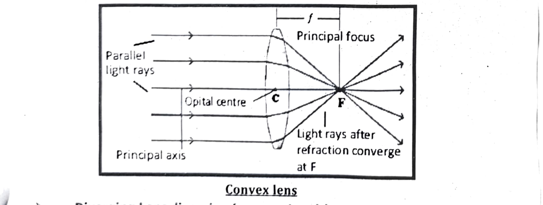
A converging lens (convex) will focus parallel rays of light to a single point called the focal point, while a diverging lens (concave) will cause parallel rays of light to spread out as if they originated from a point behind the lens.
Converging Lens (convex lens):
- Shape: A converging lens is thicker in the middle and thinner at the edges.
- Action: When parallel light rays pass through a converging lens, they are bent inward (refracted) and converge, or come together, at the focal point.
- Focal Point: The focal point is the location where the light rays converge after passing through the lens.
Diverging Lens diverging (concave Lens) lenses:
- Shape: A diverging lens is thinner in the middle and thicker at the edges.
- Action: When parallel light rays pass through a diverging lens, they are bent outward (refracted) and diverge, spreading out as if they were originating from a point behind the lens.
- Focal Point: The focal point for a diverging lens is the point from which the diverging rays appear to originate.
Concave lens
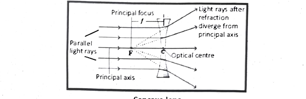
Image Formation in Converging Lens / Convex Lens:
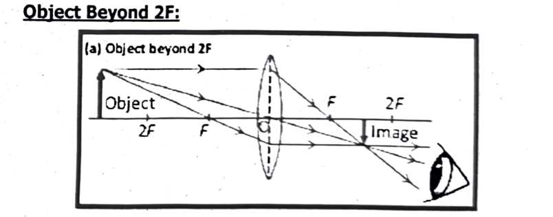
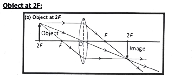
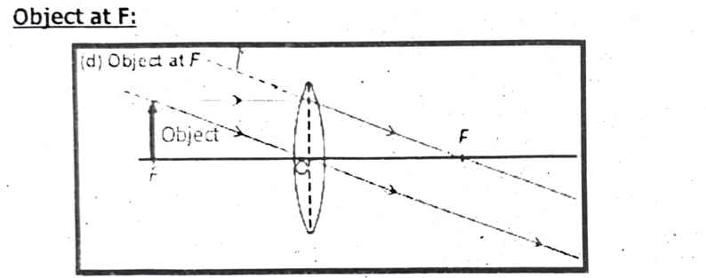
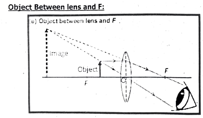
Now we explain image formation with ray diagrams for objects placed at different positions from a convex lens as shown in Fig.
(a) Object Beyond 2F:
The image is between F and 2F, real, inverted, smaller than the object.
(b) Object at 2F:
The image is at 2F, real, inverted, the same size as the object.
(c) Object Between F and 2F:
The image is beyond 2F, real, inverted, larger than the object.
(d) Object at F:
No image is formed because the refracted rays are parallel and never meet.
(e) Object Between lens and F:
The image is behind the object, virtual, erect, larger than the object.
| Image formation by Convex Lens | |||
|---|---|---|---|
| Object location | Image location | Image nature | Image size |
| Infinity | At F₂ | Real and Inverted | Diminished; point sized |
| Beyond 2F₁ | Between 2F₂ and F₂ | Real and Inverted | Diminished |
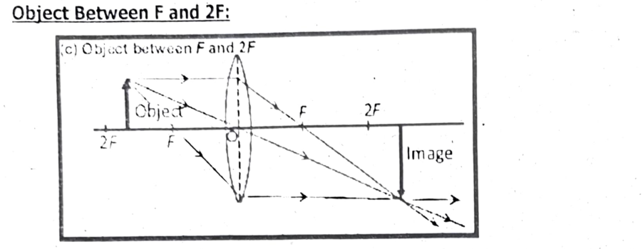
| Between 2F1 and F1 | Beyond 2F2 | Real and Inverted | Enlarged |
| At F1 | At infinity | Real and Inverted | Infinitely large or highly enlarged |
| At 2F1 | At 2F2 | Real and Inverted | Same size |
| Between F1 and O | On the same side as the object | Virtual and Erect | Enlarged |
Difference Between Real Image and Virtual Image:
| Real Image | Virtual Image |
|---|---|
| (i) A real image is generated when light rays from an object collide after reflections or refraction. | (i) A virtual image is generated when light rays from an object need not meet but pretend to meet when generated backward. |
| (ii) Converging rays create real images. | (ii) Diverging rays create virtual images. |
| (iii) On a screen, real pictures may be projected or seen. | (iii) Virtual pictures are not visible or projectable on a screen. |
| (iv) A convex lens and concave mirror create real images. | (iv) A concave lens and convex mirror create virtual images. |
| (v) An inverted image is formed. | (v) An erect image is formed. |
| (vi) The image created on the movie screen is a classic example of a real image. | (vi) The image generated in the mirror when we appear in front of it is a typical example of a virtual image. |
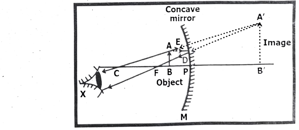
Ray Diagram of Real Image:
Real Image Examples:
Various examples where real images are formed are.
- Images formed on a screen by a lens or curved mirror
- Images formed on photographic film.
- Images formed on the retina of the eye.
- images formed by laser beams or searchlights.
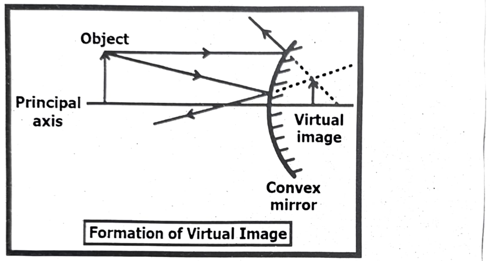
Ray Diagram of Virtual Image:
Virtual Image Examples:
Some examples of virtual images are:
- The image of an object seen in a plane mirror.
- The image seen through a plane refracting surface like glass or water.
- Retinal images in an eye with accommodation issues like myopia or hyperopia.
- Images seen through a periscope or telescope.
Linear Magnification as a Property of Thin Lenses:
Linear magnification in thin lenses describes the ratio of the image’s size to the object’s size and its orientation relative to the object. It’s a key property for understanding how lenses form images and can be calculated using the ratio of image height to object height, or the ratio of image distance to object distance.
Definition:
Linear magnification (often denoted as ‘m’) is the ratio of the image’s height (h’) to the object’s height (h), or the ratio of the image distance (d’) to the object distance (d).
Formula:
$$m = \frac{h_i}{h_o} = -\frac{d_i}{d_o}$$
Where:
- hi is the height of the image.
- $h_o$ is the height of the object.
- $d_i$ is the image distance (distance from the lens to the image).
- $d_o$ is the object distance (distance from the lens to the object).
Interpretation:
- A positive magnification indicates an upright image.
- A negative magnification indicates an inverted image.
- A magnification greater than 1 means the image is larger than the object (magnified).
- A magnification less than 1 means the image is smaller than the object (minified).
Assessment of Properties:
(i) Size of the Image:
- $|M| > 1$: The image is magnified (larger than the object).
- $|M| < 1$: The image is diminished (smaller than the object).
- $|M| = 1$: The image is the same size as the object.
(ii) Orientation of the Image:
- $M > 0$: The image is upright (erect) relative to the object. This occurs with virtual images formed by converging lenses or with combinations of lenses.
- $M < 0$: The image is inverted relative to the object. This commonly occurs with real images formed by converging lenses.
Thin Lens Equation Connection:
The thin lens equation ($\frac{1}{f} = \frac{1}{p} + \frac{1}{q}$) relates focal length ($f$), object distance ($p$), and image distance ($q$). Combining this with the magnification formula allows for the determination of image characteristics without relying on ray diagrams, particularly for converging lenses.
Diverging Lenses:
Diverging lenses (concave lenses) always produce virtual, upright, and smaller images. Their focal length is negative, and the magnification is always positive and less than 1.
Converging Lenses:
Converging lenses (convex lenses) can produce both real and virtual images, depending on the object's position relative to the focal point.
In essence, linear magnification provides a quantitative measure of how a lens affects the size and orientation of an image, which is crucial for understanding and designing optical systems.
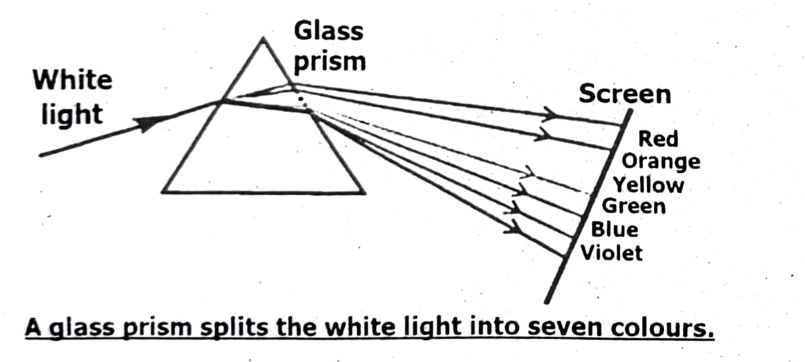
Dispersion of Light Through a Prism:
Dispersion of light through a prism is the phenomenon where white light is separated into its constituent colors (like a rainbow) when passing through a prism. This occurs because different colors of light travel at different speeds within the prism, causing them to bend (refract) at different angles.
Explanation:
- White Light Composition: White light is a combination of all colors in the visible spectrum.
- Refraction and Speed: When light travels from one medium to another (like from air to glass), it changes speed and direction, a process called refraction.
- Different Wavelengths, Different Speeds: Different colors of light have different wavelengths. This means they travel at slightly different speeds within the prism, and therefore bend at different angles.
- Separation of Colors: As a result of this varying refraction, the white light separates into its component colors, creating a spectrum.
- Order of Colors: Typically, red light is refracted the least, while violet light is refracted the most, with other colors falling in between (ROYGBIV).
Applications of Dispersion:
- Spectroscopy: Dispersion is used in spectroscopy to analyze the composition of light sources.
- Rainbows: Rainbows are formed by the dispersion of sunlight by water droplets in the atmosphere.
- Optical Instruments: Dispersion is a factor in the design of optical instruments such as lenses and prisms.
Single lenses, both convex (converging) and concave (diverging), are fundamental components in a wide range of optical devices. Convex lenses are used for magnifying, correcting farsightedness, and focusing light, while concave lenses are used for correcting nearsightedness and spreading light. They are integral to devices like magnifying glasses, eyeglasses, cameras, telescopes, microscopes, and even lasers and flashlights.
Here’s a more detailed look at their applications:
Convex (Converging) Lenses:
Magnification:
Convex lenses are the basis of magnifying glasses, allowing us to see smaller objects in more detail.
- Vision Correction: They correct farsightedness (hyperopia), where the eye focuses light behind the retina, by converging light rays onto the retina.
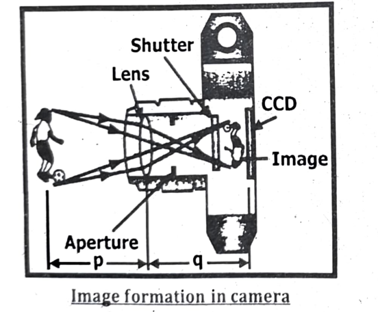
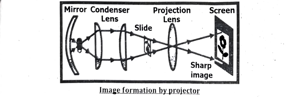
- Imaging: Cameras, telescopes, and microscopes utilize convex lenses to focus light and form images, whether it's capturing a distant landscape, celestial objects, or microscopic details.
- Lasers: In some laser applications, convex lenses can be used to focus the laser beam.
Concave (Diverging) Lenses:
- Vision Correction: Concave lenses correct nearsightedness (myopia), where the eye focuses light in front of the retina, by diverging light rays before they reach the eye.
- Spreading Light: They can be used in flashlights or other lighting devices to broaden the area of illumination.
- Lasers: Concave lenses are used to spread out the laser beam in certain applications, preventing damage to equipment or focusing on larger areas.
- Specialized Applications: They are also used in some scientific instruments and for specific optical setups.
Other Applications:
- Eyeglasses: Both convex and concave lenses are used in eyeglasses to correct a range of vision problems.
- Microscopes: Compound microscopes use a combination of lenses, including convex lenses, to achieve high magnification.
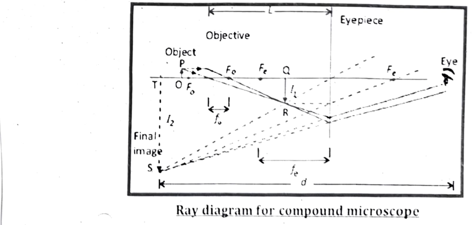
Relation for magnification of compound microscope:
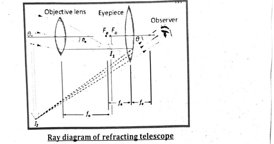
Telescopes:
Telescopes also utilize convex lenses (or mirrors, in reflecting telescopes) to gather and focus light from distant objects.
Analysis of the Visible Spectrum of Electromagnetic Radiations:
The visible spectrum is a narrow band within the broader electromagnetic spectrum that is detectable by the human eye. It ranges from approximately 380 to 700 nanometers, with each wavelength perceived as a different color. This range includes the familiar colors of the rainbow: red, orange, yellow, green, blue, indigo, and violet.
Explanation:
Wavelength and Color:
Different wavelengths within the visible spectrum correspond to different colors. Longer wavelengths (around 700 nm) are perceived as red, while shorter wavelengths (around 400 nm) are perceived as violet.
Not a Sharp Boundary:
The transitions between colors are not abrupt; they blend smoothly into one another, like the colors in a rainbow.
Part of the Larger Spectrum:
The visible spectrum is just a small portion of the electromagnetic spectrum, which includes other forms of radiation like radio waves, infrared, ultraviolet, X-rays, and gamma rays.
Importance to Humans:
The visible spectrum is crucial for our perception of the world around us, allowing us to see objects, colors, and light.
Beyond Human Perception:
While the human eye can only detect a limited range, other organisms have evolved to see different parts of the electromagnetic spectrum, like some insects that can see ultraviolet light.
Colors and Wavelengths:
The visible spectrum is composed of different colors, each corresponding to a specific range of wavelengths:
- Violet: 400–450 nm (highest frequency, highest energy)
- Indigo: 450–485 nm
- Blue: 485–500 nm
- Green: 500–565 nm
- Yellow: 565–590 nm
- Orange: 590–625 nm
- Red: 625–700 nm (lowest frequency, lowest energy)
Applications:
- Vision: The visible spectrum is essential for human vision and allows us to perceive the world around us.
- Photography: Cameras use lenses and sensors to capture and record images in the visible spectrum.
- Displays: Computer screens, televisions, and other displays emit light in the visible spectrum to create images.
- Lighting: Light bulbs and other lighting devices emit light in the visible spectrum to illuminate our surroundings.
Human Eye and Color Perception:
The human eye is a complex organ that allows us to perceive light and color. Here’s an overview of the key components and processes involved:
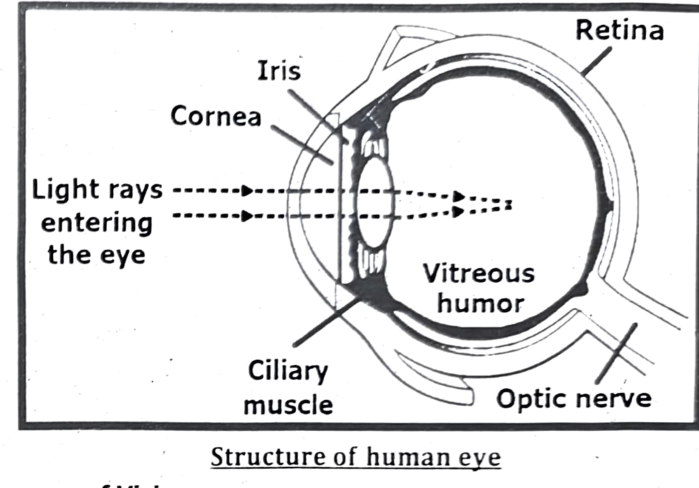
Structure of the Eye:
- Cornea: The transparent outer layer that helps to focus light.
- Iris: The colored part of the eye that controls the size of the pupil.
- Pupil: The opening in the center of the iris through which light enters the eye.
- Lens: A flexible structure that focuses light onto the retina.
- Retina: The light-sensitive layer at the back of the eye that contains photoreceptor cells (rods and cones).
- Rods: Photoreceptor cells that are sensitive to low light levels and responsible for night vision.
- Cones: Photoreceptor cells that are responsible for color vision and function best in bright light.
- Optic Nerve: Transmits signals from the retina to the brain.
Color Perception:
- Cones and Color Sensitivity: There are three types of cones, each sensitive to different ranges of wavelengths of light:
- S-cones (Short-wavelength): Most sensitive to blue light.
- M-cones (Medium-wavelength): Most sensitive to green light.
- L-cones (Long-wavelength): Most sensitive to red light.
- Trichromatic Theory: Color perception is based on the relative stimulation of these three types of cones.
For example:
- Red light stimulates the L-cones more than the M- or S-cones.
- Green light stimulates the M-cones more than the L- or S-cones.
- Blue light stimulates the S-cones more than the L- or M-cones.
- Brain Interpretation: The brain interprets the signals from the cones to perceive different colors.
- Cones and Color Sensitivity: There are three types of cones, each sensitive to different ranges of wavelengths of light:
- Color Blindness: Color blindness occurs when one or more types of cones are missing or malfunctioning, leading to an inability to distinguish certain colors.
Structure of human eye
iii. Process of Vision:
- Light Enters the Eye: Light passes through the cornea and pupil.
- Lens Focuses Light: The lens changes shape to focus light onto the retina.
- Photoreceptors Activate: Light stimulates the rods and cones in the retina.
- Signals Transmitted: The rods and cones convert light into electrical signals that are transmitted to the brain via the optic nerve.
- Brain Interprets Signals: The brain processes the signals to create an image and perceive color.
Ans:
Short-Sightedness (Myopia) and Long-Sightedness (Hyperopia):
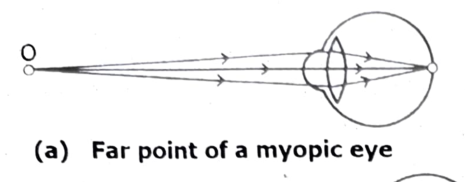
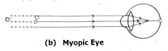
Short-Sightedness (Myopia):
- Definition: Myopia is a vision condition in which close objects appear clear, but distant objects appear blurry.
- Cause: Myopia typically occurs when the eyeball is too long or the cornea is too curved. This causes light to focus in front of the retina instead of directly on it.
- Image Formation: The image of a distant object is formed in front of the retina.
- Correction: Myopia is corrected using diverging (concave) lenses. These lenses spread out the light rays before they enter the eye, effectively moving the focal point back onto the retina.
Correction of Near Sightedness / Short Sightedness
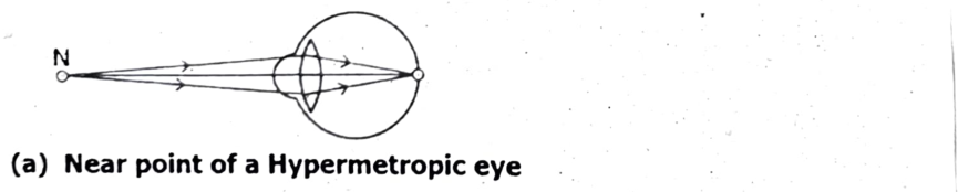
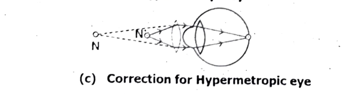
Long-Sightedness (Hyperopia):
- Definition: Hyperopia is a vision condition in which distant objects appear clear, but close objects appear blurry.
- Cause: Hyperopia typically occurs when the eyeball is too short or the cornea is not curved enough. This causes light to focus behind the retina instead of directly on it.
- Image Formation: The image of a close object is formed behind the retina.
- Correction: Hyperopia is corrected using converging (convex) lenses. These lenses bend the light rays inward before they enter the eye, effectively moving the focal point forward onto the retina.
Correction of Far Sightedness / Long Sightedness


| Feature | Short-Sightedness (Myopia) | Long-Sightedness (Hyperopia) |
|---|---|---|
| Clarity | Close objects clear | Distant objects clear |
| Distant Vision | Blurry | Clear |
| Close Vision | Clear | Blurry |
| Cause | Elongated eyeball | Shortened eyeball |
| Focal Point | In front of retina | Behind retina |
| Correcting Lens | Diverging (concave) | Converging (convex) |
Gravitational Lensing:
Gravitational lensing is a phenomenon where the gravity of a massive object bends and magnifies the light from a distant object, acting like a lens. This effect is predicted by Einstein's theory of general relativity, which describes gravity as a curvature of space time. Massive objects, like galaxies or galaxy clusters, warp space time around them, causing light traveling from a background object to follow a curved path. This bending and focusing of light can create multiple images, arcs, or rings of the background object, or even magnify its brightness.
Explanation:
General Relativity:
Einstein's theory of general relativity states that massive objects warp spacetime, and this curvature dictates how objects move through space.
Light Bending:
Light, though massless, also follows the curves of spacetime. When light passes near a massive object, its path is bent, similar to how light bends when passing through a lens.
Magnification and Distortion:
The amount of bending depends on the mass of the object and the distance of the background light source. This can lead to multiple images of the same object, or distorted arcs and rings of light.
Examples:
One well-known example is the “Einstein ring”, where a perfectly aligned background source forms a complete ring around the lensing object. More commonly, gravitational lensing creates arcs and distorted shapes of distant galaxies, allowing astronomers to study fainter, more distant objects.
Research Tool:
Gravitational lensing is not just a visual phenomenon; it’s also a powerful tool for astronomers. By studying the lensing patterns, they can infer the distribution of mass in the lensing object, including dark matter, and learn about the properties of distant galaxies that would otherwise be too faint to observe.
Applications of Gravitational Lensing:
- Studying Distant Galaxies: Gravitational lensing can magnify the light from distant galaxies, allowing astronomers to study them in greater detail.
- Mapping Dark Matter: Weak lensing is used to map the distribution of dark matter, which does not emit light but interacts gravitationally.
- Detecting Exoplanets: Microlensing can be used to detect exoplanets orbiting distant stars.
- Measuring the Hubble Constant: Gravitational lensing can be used to measure the Hubble constant, which describes the expansion rate of the universe.
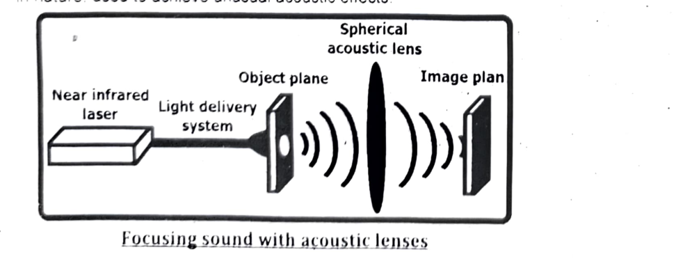
Acoustic Lensing:
Acoustic lensing is the phenomenon where sound waves are focused or redirected using specially designed structures or materials, analogous to how optical lenses manipulate light waves. It involves creating variations in acoustic impedance (resistance to sound propagation) to bend and focus sound waves.
Explanation:
Acoustic Impedance:
Acoustic impedance (Z) is a measure of how much a medium resists the passage of sound waves. It is defined as the ratio of pressure (p) to particle velocity (v): $Z=\frac{p}{v}$.
Differences in acoustic impedance between two materials cause sound waves to reflect or refract at the interface.
Refraction of Sound:
When sound waves pass from one medium to another with a different acoustic impedance, they bend (refract). The amount of bending depends on the difference in acoustic impedance and the angle of incidence.
Acoustic Lenses:
Acoustic lenses are designed to manipulate sound waves in a controlled manner. They can be made from various materials and structures, such as:
- Solid Lenses: Made from materials with different acoustic properties, shaped to focus or diverge sound waves.
- Phononic Crystals: Periodic structures with varying acoustic impedance that can be designed to control sound propagation.
- Metamaterials: Artificially engineered materials with properties not found in nature, used to achieve unusual acoustic effects.
Applications of Acoustic Lensing:
Medical Imaging:
- Ultrasound Focusing: Acoustic lenses are used to focus ultrasound waves for high-resolution medical imaging.
- Therapeutic Ultrasound: Focused ultrasound can be used to deliver targeted energy for non-invasive treatments, such as tumor ablation.
Non-Destructive Testing (NDT):
- Material Inspection: Acoustic lenses are used to focus sound waves for detecting defects and anomalies in materials without damaging them.
Underwater Acoustics:
- Sonar Systems: Acoustic lenses are used to improve the performance of sonar systems for underwater navigation, communication, and detection.
Architectural Acoustics:
- Sound Focusing: Acoustic lenses can be used to focus sound in auditoriums or concert halls to improve the listening experience.
Acoustic Microscopy:
- High-Resolution Imaging: Acoustic lenses are used to focus sound waves for high-resolution imaging of small structures and materials.
Particle Manipulation:
- Acoustic Tweezers: Focused sound waves can be used to manipulate and move small particles or cells.