
Constructed Response Questions:
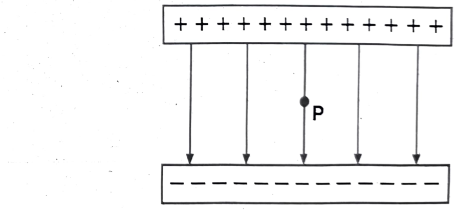
Q1. (a) In your notebook, draw two parallel lines representing metal plates, one positive and one negative. (b) Eight negative point charges of equal magnitude are distributed evenly around a circle. Sketch the electric field in the region around and within this charge distribution. Explain how this charge distribution can be used to model the electric field inside a coaxial cable.
(a)
To represent two parallel metal plates with opposite charges, draw two horizontal lines that are parallel to each other. Above the top line, write “+”, indicating a positive charge. Below the bottom line, write “−”, indicating a negative charge. This setup creates an electric field between the two plates, with field lines originating from the positive plate and terminating on the negative plate.
(b)
Eight Negative Charges and Coaxial Cable Model:
A distribution of eight negative point charges equally spaced around a circle creates an electric field with lines pointing inward towards the center of the circle. This field is strongest near the charges and weakest in the center. This configuration can be used to model the electric field inside a coaxial cable by representing the inner conductor as a line of positive charge and the outer conductor as a cylindrical shell of negative charge. The electric field is then confined between the two conductors.
Modeling a Coaxial Cable:
- Inner Conductor: Imagine the center of the circle is replaced by a positively charged wire (positive line charge).
- Outer Conductor: Enclose the circle of negative charges with a cylindrical shell (outer conductor).
- Electric Field: The electric field lines will now be radially directed from the inner positive wire towards the outer negative cylindrical shell. The field lines will be confined within the space between the inner wire and the outer shell.
Explanation:
- In a coaxial cable, the inner conductor carries a positive charge, and the outer conductor carries an equal and opposite negative charge.
- This charge distribution creates an electric field that is primarily radial, extending from the inner conductor to the outer conductor.
- The electric field lines are strongest near the conductors and diminish as you move away from them.
- In the region between the conductors, the electric field is relatively uniform, similar to the field created by the distribution of negative charges around a circle.
- The electric field within the conductors themselves is zero due to electrostatic equilibrium.
By approximating the coaxial cable as a line of positive charge surrounded by a circle of negative charges, we can understand the basic behavior of the electric field in this common type of cable. The field is confined between the two conductors, and its strength is related to the charge density and distance between the conductors.
Q2. Figure shows a source that consists of two charged particles. (a) What is the sign of the charge on each particle? (b) In which region (A, B, C or D) is the electric field the weakest? (c) In which region (A, B, C or D) is the electric field the strongest?
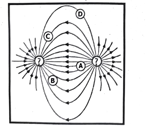
Here’s the analysis of the electric field based on the provided figure:
(a) Sign of the charges
- Electric field lines originate from positive charges and terminate at negative charges.
- In the figure, the electric field lines point from the particle on the right towards the particle on the left.
- Therefore, the particle on the right is positive, and the particle on the left is negative.
(b) Weakest electric field
- Electric field strength is represented by the density of field lines.
- The electric field is weakest where the field lines are most spread out.
- In the figure, the region with the most spread-out field lines is region D.
(c) Strongest electric field
- Electric field strength is strongest where the field lines are closest together.
- In the figure, the field lines are closest together in region A.
- Therefore, the electric field is strongest in region A.
Short Questions:
Q1. What is the relationship between charge and mass when a metal becomes charged, and assess whether the mass change is significant?
When a metal object becomes charged, its mass changes very slightly due to the addition or removal of electrons. Negatively charged objects gain mass, as they gain electrons, while positively charged objects lose mass, as they lose electrons. However, the mass change is extremely small, practically immeasurable, because electrons have such tiny mass compared to the overall mass of the object.
Explanation:
Charge and Electrons:
An object becomes charged when it gains or loses electrons. Electrons carry a negative charge.
Negative Charge:
If an object gains electrons, it becomes negatively charged. The mass of the object increases slightly because electrons are added.
Positive Charge:
If an object loses electrons, it becomes positively charged. The mass of the object decreases slightly because electrons are removed.
Mass of Electrons:
Electrons are incredibly light particles. Their individual mass is approximately $m_e \approx 9.11 \times 10^{-31}\ \text{kg}$. This is minuscule compared to the mass of even a small metal object.
Insignificant Mass Change:
Even if a large number of electrons are added or removed to create a significant charge (e.g., a Coulomb), the resulting mass change is still extremely small and usually undetectable with conventional measurement tools. The mass change is often on the order of micrograms or even nano grams, while the mass of the object itself is typically in grams or kilograms.
Q2. How do grounding systems prevent static buildup in fuel trucks, what are the dangers without grounding?
Grounding systems prevent static buildup in fuel trucks by providing a conductive path for static electricity to dissipate to the earth, preventing the accumulation of charge that could lead to sparks and potentially ignite fuel vapors. Without proper grounding, the static charge buildup can cause sparks, which can ignite flammable fuel vapors, leading to fires or explosions.
Q3. Why do electrons transfer charge instead of protons or neutrons, and how does this affect circuit and device design?
Electrons are responsible for transferring charge in most electrical phenomena because they are loosely bound to atoms and can move relatively easily, while protons are tightly held within the nucleus and require significant energy to be dislodged. This difference in mobility and binding energy dictates that electrons are the primary charge carriers in circuits and devices.
- Component Design: Electronic components like resistors, capacitors, and transistors are designed to control and manipulate the flow of electrons. For example, resistors impede electron flow, while transistors act as switches by controlling electron flow.
- Circuit Analysis: Understanding electron behavior is fundamental to analyzing and designing electrical and electronic circuits. Engineers use circuit diagrams and mathematical equations to predict and control the flow of electrons in complex systems.
Q4. Why does a charged balloon stick to a neutral wall due to polarization? Compare the interaction with a conductor vs. an insulator.
Polarization and How a Charged Balloon Sticks to a Neutral Wall:
A charged balloon sticks to a neutral wall due to polarization, where the charged balloon induces a separation of charge within the wall, creating a net attractive force. This attraction occurs even though the wall remains overall neutral.
- Conductors allow free charge movement, so a charged balloon near a conductor causes charges to flow to or away from the balloon, leading to a strong attraction or repulsion.
- Insulators, while not allowing free charge flow, can still have their molecules slightly shift their charge distribution (polarize), allowing for the same type of attractive force as seen with the wall.
Explanation:
(i) Polarization:
When a charged balloon is brought near a neutral wall, it repels electrons (if the balloon is negatively charged) or attracts them (if the balloon is positively charged) in the wall's atoms. This causes a slight shift in the distribution of charge within the wall's atoms or molecules, with the side closest to the balloon becoming oppositely charged. This is called polarization.
(ii) Attraction:
Because the side of the wall closest to the balloon has an opposite charge, there is an attractive force between the balloon and the wall. Even though the overall charge of the wall remains neutral, the polarized charges create a net attractive force, causing the balloon to stick.
(iii) Conductors vs. Insulators:
- Conductors: In conductors, charges are free to move. If a negatively charged balloon is brought near a conductor, electrons in the conductor will move away from the balloon, creating a region of positive charge near the balloon. This results in a strong attractive force. If the balloon were positively charged, electrons would move towards it, creating a region of negative charge and a strong attractive force as well.
- Insulators: In insulators, charges are not free to move easily. However, the atoms or molecules within the insulator can still be polarized, meaning their positive and negative charges can shift slightly, creating a separation of charge. This allows for the same type of attractive force seen with the wall. While the movement of charge is not as extensive as in a conductor, the polarization effect is still sufficient to cause the balloon to stick.
Q5. How do positive and negative charges behave differently in an electric field?
Behavior of Positive and Negative Charges in an Electric Field:
In an electric field, positive and negative charges experience forces in opposite directions. A positive charge will be pushed in the direction of the electric field lines, while a negative charge will be pushed in the opposite direction. This fundamental difference stems from the way electric fields interact with charges: like charges repel, and opposite charges attract.
Q6. What are the effects of changing electric field direction or strength in applications like capacitors?
Changing the direction of the electric field applied to a capacitor causes the capacitor to either charge or discharge, depending on the direction of the change. If the applied voltage increases, the capacitor will draw current and store energy, effectively acting as a load.
- Conversely, if the voltage decreases, the capacitor will release stored energy, supplying current and acting as a source. This behavior is due to the capacitor’s ability to store energy in an electric field and its tendency to oppose changes in voltage.
- Changing the electric field strength within a capacitor primarily affects its capacitance and voltage. Increasing the electric field strength (by reducing the distance between plates or increasing the voltage) will increase the voltage across the capacitor and decrease its capacitance.
- Conversely, decreasing the electric field strength (by increasing the distance between plates or decreasing the voltage) will decrease the voltage and increase the capacitance.
Q7. Compare electric and gravitational fields in terms of strength, range, and forces, and evaluate situations where both fields affect objects.
Comparison between electric and gravitational fields:
Electric and gravitational fields both describe forces acting at a distance, but they differ significantly in their origins, the types of forces they mediate, and their relative strengths. Electric fields arise from electric charges and can be attractive or repulsive, while gravitational fields originate from mass and are always attractive. The strength of an electric field depends on the charge and distance, while gravitational field strength depends on mass & distance.
Here’s a more detailed comparison:
Strength:
- Electric fields: Electric field strength is proportional to the charge creating the field and inversely proportional to the square of the distance from the charge.
- Gravitational fields: Gravitational field strength is proportional to the mass creating the field and inversely proportional to the square of the distance from the mass.
- Relative Strength: Electric forces are generally much stronger than gravitational forces at the atomic and molecular level. For instance, the electric force between an electron and a proton is significantly stronger than the gravitational force between them.
Range:
- Electric fields: Electric field lines originate from positive charges and terminate on negative charges, extending to infinity.
- Gravitational fields: Gravitational field lines extend from a mass to infinity, and while their strength decreases with distance, they never truly end.
Forces:
- Electric fields: Electric forces can be attractive or repulsive, depending on the charges involved (opposite charges attract, like charges repel).
- Gravitational fields: Gravitational forces are always attractive, pulling objects with mass towards each other.
Situations Where Both Fields Affect Objects:
- Planetary Motion: Planets orbit stars due to the gravitational force between them. At the same time, the planets and stars are made of charged particles, so they also exert electric forces on each other. However, the gravitational force is dominant at the astronomical scale due to the large masses involved.
- Atoms: Atoms are composed of positively charged protons and negatively charged electrons. The electrons are held in orbit around the nucleus by the attractive electric force between them. Additionally, the gravitational force exists between all the particles in the atom, but it is negligible compared to the electric force.
- Charged Particles in Magnetic Fields: Charged particles moving in a magnetic field experience a force due to the magnetic field. This force is perpendicular to both the velocity of the charged particle and the magnetic field direction. However, since magnetic fields are generated by moving charges, there is also an electric field present, which can exert a force on the charged particle.
Q8. Can insulators be charged by induction, under what conditions does this happen, and what are alternative methods for charging insulators?
No, insulators cannot be charged by electrostatic induction in the same way conductors can. While insulators can be polarized, meaning their internal charges can be rearranged, they cannot be charged with a net excess charge through induction. This is because insulators lack the free electrons necessary for charge to move and separate, as required for induction to create a net charge.
Why Insulators Can’t Be Charged by Induction:
Insulators: Insulators, on the other hand, do not have free electrons. Their electrons are tightly bound to their atoms, making it difficult for charge to move and separate. While insulators can be polarized, the charge separation is temporary and limited, and no net charge can be established through induction.
Alternative Methods for Charging Insulators:
Contact:
If a charged insulator is brought into contact with a neutral insulator, some of the charge may be transferred to the neutral insulator, but this is not a true induction process.
Specialized Techniques:
Some specialized techniques can be used to create temporary charge separation in insulators, such as using high-voltage corona discharge, but these methods are not equivalent to conventional charging by induction.
In essence, while insulators can exhibit polarization, they cannot be charged by induction in the same way conductors can, due to the fundamental difference in their electron mobility.
Q9. What is corona discharge around conductors, especially sharp points?
Corona discharge is an electrical discharge that occurs when the air surrounding a high-voltage conductor becomes ionized, forming a luminous glow, especially around sharp points or edges. This happens because the electric field intensity at these points is significantly higher than elsewhere on the conductor, leading to the ionization of air molecules and the subsequent release of energy in the form of light and heat.
Explanation:
High Electric Field:
Sharp points on a conductor create a concentrated electric field. The field strength is inversely proportional to the radius of curvature, so sharp points have a much higher field strength than rounded surfaces.
Ionization:
When the electric field strength exceeds the dielectric strength of the surrounding air (around 30 kV / cm), air molecules become ionized, meaning they lose or gain electrons, forming ions and free electrons.
Electron Avalanche:
These free electrons are accelerated by the electric field and collide with other air molecules, creating more ions and electrons, resulting in an “electron avalanche” effect.
Corona Discharge:
The recombination of ions and electrons, along with the excitation and de-excitation of atoms, releases energy in the form of light (a faint glow) and heat, which is the corona discharge.
Sharp Points:
Sharp points concentrate the electric field, making it easier to reach the breakdown voltage of air, thus initiating corona discharge at these locations.
Other Factors:
Corona discharge can also occur at other locations where the electric field is concentrated, such as edges, small diameter wires, and even during stormy weather.
Effects of Corona Discharge:
Power Loss:
Corona discharge represents a loss of electrical energy, as current leaks from the conductor into the surrounding air.
Noise and Interference:
The ionization process can produce radio frequency interference (RFI) and audible noise, often described as a hissing or crackling sound.
Material Degradation:
Corona discharge can generate ozone and other reactive gases that can corrode and degrade the materials of the conductor and surrounding insulators.
Damage:
In extreme cases, uncontrolled corona discharge can lead to complete electrical breakdown and arcing, causing significant damage to equipment.
Applications:
Despite being often undesirable, corona discharge has some useful applications, including:
- Ozone Generation: Controlled corona discharges are used in ozone generators for various applications like water treatment and air purification.
- Particle Removal: Corona discharge can be used to remove particulate matter from air or gas streams.
- Material Treatment: Corona discharges can modify the surface properties of materials, making them more suitable for specific applications.
Q10. How does electric field concentration cause ionization, and what are its practical uses or problems?
High electric field concentrations can cause ionization by accelerating free electrons to high speeds, which then collide with neutral atoms or molecules, transferring enough energy to eject electrons and create ions. This process can lead to a cascade effect, known as an avalanche breakdown, resulting in a spark or arc. Practical applications include ion sources in mass spectrometry and industrial processes, while problems include electrical breakdown in high-voltage equipment and lightning strikes.
How Electric Field Concentration Causes Ionization:
Field Strength:
When an electric field is very strong, it exerts a significant force on charged particles, including free electrons.
Electron Acceleration:
This force accelerates these electrons, giving them high kinetic energy.
Collisions and Ionization:
When these fast-moving electrons collide with neutral atoms or molecules, they can transfer enough energy to knock off an electron, creating an ion pair (a positively charged ion and a free electron).
Avalanche Breakdown:
The newly created free electrons are also accelerated by the electric field, leading to further collisions and ionization. This creates a chain reaction, known as an avalanche, which can quickly multiply the number of ions.
Spark or Arc Formation:
If the ionization process is sustained, it can lead to a spark or even a continuous flow of current, known as an arc, as the ionized gas becomes conductive.
Practical Uses:
Ion Sources in Mass Spectrometry:
Field ionization (FI) and field desorption (FD) are techniques used to ionize molecules for analysis in mass spectrometers.
Industrial Applications:
Electric fields are used in processes like electrostatic painting, where charged paint particles are attracted to grounded objects, and in air filtration systems, where particles are charged and then collected on oppositely charged plates.
Problems Associated with Electric Field Concentration:
Electrical Breakdown:
In high-voltage equipment, such as power lines and transformers, strong electric fields can cause the surrounding air or insulation to ionize, leading to electrical breakdown, which can cause arcing and damage.
Lightning:
Lightning is a dramatic example of ionization caused by a strong electric field in the atmosphere. Thunderclouds build up large static charges, and when the electric field becomes strong enough, it can lead to a discharge of electricity in the form of a lightning strike.
Corona Discharge:
At high voltages, sharp edges or points can create localized areas of high electric field concentration, leading to corona discharge, which is a visible glow and can cause power loss or interference.
Q11. What causes Lichtenberg figures to form after lightning strikes, why don’t they always appear?
Lichtenberg figures, also known as “lightning flowers” or “lightning trees”, are fern-like, reddish marks that appear on the skin after a lightning strike. They are caused by the rupture of capillaries beneath the skin due to the electrical discharge. These marks are a natural example of fractals and are thought to be a result of the current spreading out, causing ionization and heat effects. They don’t always appear because the exact mechanism of their formation is still not fully understood, and various factors like the intensity of the strike, skin moisture, and individual susceptibility to capillary damage can influence their appearance.
Here’s a more detailed explanation:
Formation:
Electrical Discharge:
When lightning strikes, it releases a massive electrical discharge that travels through the body.
Capillary Rupture:
This electrical energy can damage the tiny blood vessels (capillaries) just beneath the skin.
Ionization and Heat:
The current also causes ionization and heat effects, further contributing to the damage.
Lichtenberg Figures:
The combination of these factors leads to the rupture of capillaries and the leakage of red blood cells into the surrounding tissue, creating the characteristic fern-like patterns.
Why they don’t always appear:
Intensity of Strike:
The severity of the lightning strike can vary, and if the current is too weak or the duration is short, it may not cause significant capillary damage visible as Lichtenberg figures.
Skin Moisture:
The presence of moisture on the skin can affect how the current spreads. More moisture may lead to the figures being more pronounced, while drier skin might not show them as clearly.
Individual Susceptibility:
People have different skin types and sensitivities, and some individuals may be more prone to capillary rupture than others.
Depth of Damage:
If the electrical current penetrates deeply into the skin, it may not result in the superficial, branching patterns of Lichtenberg figures.
Healing:
The marks can fade within a few hours or days as the body begins to heal the damaged capillaries.
In summary, while Lichtenberg figures are a common indicator of a lightning strike, their appearance is influenced by the intensity of the strike, the moisture level of the skin, and individual factors, making them not always present after every lightning strike.
Q12. How do lightning rods protect buildings, what is the role of pointed rods in attracting discharge?
Lightning Rods Protect Buildings:
Lightning rods protect buildings by providing a safe, conductive path for lightning to travel to the ground, thus preventing damage to the structure. The pointed tip of the rod plays a crucial role by creating a strong electric field that attracts the downward-traveling leader of a lightning strike, guiding it away from the building.
Explanation:
Attraction and Capture:
Lightning rods are designed to be the highest point on a structure and are made of conductive materials like copper or aluminum. During a thunderstorm, the potential difference between the cloud and the ground creates a strong electric field. This field causes a streamer to travel upwards from the lightning rod’s pointed tip, meeting the downward-traveling leader of the lightning strike.
Conduction:
Once the lightning strike connects with the rod, the electrical current is channeled through the conductive rod and down a grounding wire connected to the rod.
Grounding:
The grounding wire ensures that the electrical current is safely dissipated into the earth, preventing it from traveling through the building’s structure, which could cause fires or other damage.
Pointed Tip:
The pointed tip of the lightning rod is essential because it concentrates the electric field, making it easier for the rod to attract the lightning strike. A blunt or rounded surface would create a weaker electric field and might not be as effective in attracting the strike.
Q13. How can lightning rod design and placement be optimized for better protection?
Optimizing Lightning Rod Design:
To optimize lightning rod design and placement for enhanced protection, focus on maximizing interception efficiency by strategically positioning air terminals on the highest points of a structure and ensuring they are connected to a robust grounding system. Use methods like the rolling sphere or protective angle to define the protected area and ensure all vulnerable points are covered, while also considering the structure’s specific characteristics and potential hazards.
(i) Understanding the Basics:
Air Terminals:
These are the rods that directly intercept lightning strikes, acting as the first line of defense.
Conductors:
These are the pathways (typically wires or cables) that safely conduct the lightning current from the air terminals to the grounding system.
Grounding System:
This is a network of electrodes buried in the earth that dissipates the lightning current into the ground.
(ii) Design and Placement Strategies:
Maximize Interception:
Place air terminals at the highest points of a structure, including peaks, corners, and other elevated features.
Rolling Sphere Method:
This method simulates a rolling sphere over the structure. Any point the sphere touches is considered vulnerable and should be protected by an air terminal.
Protective Angle Method:
This method creates a cone-shaped protective area around the air terminal, with the angle determined by the lightning protection level and structure’s height.
Mesh Method:
Install a network of conductors across the roof, creating a mesh that intercepts lightning and provides protection to a wider area.
Consider Structure’s Characteristics:
For complex structures, a combination of methods may be needed. Pay attention to protruding features, metallic components, and the overall shape of the building.
(iii) Material Selection and Installation:
Air Terminals:
Use durable, highly conductive materials like copper, aluminum, or stainless steel.
Conductors:
Ensure conductors are large enough to handle the lightning current and are securely connected to the air terminals and grounding system.
Grounding System:
Use low-resistance materials like copper or galvanized steel and ensure proper electrode installation for effective dissipation.
Bonding:
Ensure all metallic components on the structure are properly bonded to the lightning protection system to prevent side flashing.
(iv) Specific Considerations:
PV Systems:
For solar panel installations, consider separate lightning protection systems for the PV array, especially if located near existing building lightning protection.
Residential Buildings:
Conduct a risk assessment to determine the need for lightning protection, considering factors like building height, location, and occupancy.
Commercial Buildings:
Follow relevant standards (e.g., IEC 62305) and consider specialized methods for larger or more complex structures.
By carefully considering these factors and implementing a well-designed lightning protection system, you can significantly reduce the risk of damage and ensure the safety of your structure and its occupants.
Long Questions:
Q1. Explain electrification and how charge conservation and quantization govern particle behavior, with real-world examples like electronics.
Electrification:
Electrification is the process of charging an object, typically by adding or removing electrons. There are several ways this can happen:
Friction (Triboelectric Effect):
Rubbing two dissimilar materials together can transfer electrons from one to the other. For example, rubbing a glass rod with silk will cause the glass to become positively charged (losing electrons) and the silk to become negatively charged (gaining electrons).
Conduction:
Bringing a charged object into contact with a neutral object can transfer charge. If the objects are conductors, the charge will spread out over both objects.
Induction:
Bringing a charged object near a neutral, conductive object can cause a redistribution of charge within the neutral object. For example, if a negatively charged rod is brought near a neutral metal sphere, electrons in the sphere will be repelled away from the rod, leaving a positive charge on the side of the sphere closest to the rod.
Charge Conservation:
The law of charge conservation states that the total electric charge in an isolated system remains constant. In other words, charge cannot be created or destroyed, only transferred from one object to another.
Example:
When you rub a balloon on your hair, electrons are transferred from your hair to the balloon. The balloon becomes negatively charged, and your hair becomes positively charged. The total amount of negative charge on the balloon is equal to the total amount of positive charge on your hair. The total charge of the isolated system (balloon + hair) remains constant.
Charge Quantization:
Charge quantization means that electric charge comes in discrete units. The smallest unit of charge is the elementary charge, denoted by $e$, which is the magnitude of the charge of a single electron or proton ($e \approx 1.602 \times 10^{-19}$ Coulombs). All observable charges are integer multiples of this elementary charge. You can have a charge of $+e$, $-e$, $+2e$, $-3e$, etc., but you cannot have a charge of, say, $1.5e$.
How Charge Conservation & Quantization Govern Particle Behavior (Electronics):
These principles are fundamental to how electronic devices work:
Electric Circuits:
In a circuit, charge (carried by electrons) flows from one point to another. The total amount of charge entering a circuit element must equal the total amount of charge leaving it (charge conservation).
Semiconductors:
Semiconductors, like silicon, are the building blocks of transistors and integrated circuits. Their behavior is governed by the movement of charge carriers (electrons and “holes”, which act as positive charges). By controlling the flow of these charge carriers, we can create electronic devices that perform a wide variety of functions. The number of these charge carriers is always affected by the charge quantization rule.
Digital Electronics:
Digital circuits rely on the manipulation of discrete voltage levels (representing 0s and 1s). These voltage levels are created by controlling the flow of electrons, and the amount of charge involved is always a multiple of the elementary charge.
Capacitors:
Capacitors store electrical energy by accumulating electric charge on two conductive plates separated by an insulator. The amount of charge stored is proportional to the voltage across the capacitor. The charge on the plates is, of course, quantized.
Q2. Describe how objects gain charge through triboelectric effects and how they behave when in contact with conductors.
Triboelectric Effect:
The triboelectric effect is a type of contact electrification where materials become electrically charged after rubbing against each other. This happens because electrons transfer between the materials, with one material gaining electrons (becoming negatively charged) and the other losing them (becoming positively charged). When these charged objects come into contact with conductors, the excess charge can redistribute, potentially leading to a discharge if the conductor is grounded or if the charge builds up to a high enough potential.
How Objects Gain Charge through Triboelectric Effects:
Contact and Friction:
When two different materials are rubbed together, their surfaces come into close contact and experience friction.
Electron Transfer:
This friction can cause electrons (negatively charged particles) to transfer from one material to the other.
Charge Separation:
One material ends up with a surplus of electrons (negative charge), while the other has a deficiency (positive charge).
Triboelectric Series:
Materials can be ranked in a triboelectric series based on their tendency to gain or lose electrons. When two materials from the series are rubbed, the one higher in the series becomes positive, and the one lower becomes negative.
Behavior of Charged Objects in Contact with Conductors:
Charge Redistribution:
When a charged object (e.g., a balloon rubbed against hair) comes into contact with a conductor (e.g., a metal doorknob), the excess charge will redistribute itself over the surface of the conductor.
Electrostatic Induction:
If the charged object is brought near a conductor without direct contact, it can induce a separation of charge within the conductor, creating a region of positive and negative charge.
Discharge:
If the conductor is grounded (connected to the earth), the excess charge can flow to or from the earth, neutralizing the conductor and potentially causing a spark or shock.
Attraction and Repulsion:
Like charges (positive-positive or negative-negative) will repel each other, while opposite charges (positive-negative) will attract.
Example:
- Rubbing a plastic pen on a wool sweater creates static electricity. The pen becomes negatively charged, and the sweater becomes positively charged.
- If you then touch a metal doorknob with the charged pen, the excess electrons on the pen will flow to the doorknob, potentially causing a small shock.
Q3. Compare conductors and insulators at the atomic level, focusing on electron configurations and their practical uses.
Conductors and insulators differ fundamentally in how their electrons behave at the atomic level. Conductors, like metals, have many free electrons that can easily move and carry an electrical charge, making them good at conducting electricity. Insulators, like rubber or plastic, have electrons tightly bound to their atoms, preventing them from moving freely and thus resisting the flow of electricity.
Electron Behavior at the Atomic Level:
Conductors:
In conductors, some electrons are loosely bound to the atoms and can move relatively freely throughout the material. These are often called “free electrons” or “delocalized electrons”. Scientific sources explain that the abundance of these free electrons is what enables conductors to readily conduct electricity.
Insulators:
In insulators, electrons are tightly bound to their respective atoms and cannot move freely. This lack of free electrons means that electrical current cannot easily flow through them.
Practical Uses:
Conductors:
Conductors are used in wires, circuits, and other components where electrical current needs to flow easily. Common examples include copper, aluminum, and silver.
Insulators:
Insulators are used to prevent electrical shock, reduce energy costs, and control the emission of pollutants. They are used to cover wires, create barriers in circuits, and insulate electrical components. Examples include rubber, plastic, and glass.
Q4. Evaluate charging methods (friction, conduction, induction) and their efficiency in different materials, with real-world applications.
Charging methods like friction, conduction, and induction differ in their mechanisms and suitability for various materials and applications. Friction relies on the transfer of electrons through contact and rubbing, making it effective for insulators. Conduction involves direct contact for charge transfer, best suited for conductors. Induction utilizes electric fields and
grounding to induce charge without direct contact, working with both conductors and insulators.Charging Methods and Efficiency:
Friction:
This method involves rubbing two different materials together, causing electrons to transfer from one material to the other due to their differing electron affinities. One material becomes positively charged, and the other negatively charged.
Efficiency:
The efficiency of charging by friction varies greatly depending on the materials used. Materials with a large difference in their ability to hold onto electrons will be more efficient. For example, rubbing a balloon on your hair is more effective than rubbing two balloons together.
Real-world applications:
Static cling in clothing, charging a balloon by rubbing it on your hair, and some early forms of electrostatic generators.
Conduction:
This method involves touching a charged object to a neutral object, causing charge to transfer from the charged object to the neutral object.
Efficiency:
Conduction is generally more efficient than friction for transferring charge, especially when using conductive materials. The amount of charge transferred depends on the materials’ conductivity and the contact area.
Real-world applications:
Charging a metal sphere with a charged rod, grounding a circuit, and some types of electrostatic spray painting.
Induction:
This method involves using a charged object to induce a charge on a nearby neutral object without direct contact. This is achieved by bringing a charged object close to the neutral object, which causes a redistribution of charges within the neutral object. Grounding the neutral object then allows for the removal of one type of charge, leaving the object with a net charge opposite to the inducing charge.
Efficiency:
Induction is less efficient than conduction, especially when grounding is involved. The efficiency is affected by factors like the distance between the charged object and the neutral object, and the material’s conductivity.
Real-world applications:
Photocopying, laser printers, electrostatic precipitators, and some types of wireless charging.
Q5. Design a procedure to charge two metal spheres via electrostatic induction and discuss real world uses of induction.
To charge two metal spheres via electrostatic induction, bring them into contact, then bring a charged rod near one sphere without touching it. Separate the spheres while the rod is still present, and then remove the rod. This results in the spheres having opposite charges. Real-world applications include wireless charging of devices, electrostatic precipitators, and some types of lightning rods.
Detailed Procedure:
Initial Setup:
Place two uncharged metal spheres, labeled A and B, on insulating stands (like plastic or wood) to prevent charge leakage to the ground. Ensure the spheres are touching each other.
Induction:
Bring a positively charged rod (e.g., a glass rod rubbed with silk) near sphere A, without actually touching the spheres. The positive rod will attract the negatively charged electrons within the spheres.
Charge Separation:
The electrons will be drawn towards sphere A, leaving sphere B with an excess of positive charge (due to the deficiency of electrons). This redistribution of charge is called electrostatic induction.
Separation:
While the charged rod is still in place, carefully separate the two spheres by a small distance (e.g., by moving the insulating stands apart). The separation ensures that the charge on each sphere is trapped.
Removal of the Rod:
Finally, remove the charged rod. The spheres will now be left with opposite charges: sphere A will be negatively charged, and sphere B will be positively charged.
Testing (Optional):
Bring the spheres close again, and they should attract each other due to their opposite charges.
Real-World Applications of Electrostatic Induction:
Wireless Charging:
Many electronic devices, such as smartphones and electric toothbrushes, use induction to transfer energy wirelessly from a charging base to the device. This eliminates the need for physical charging cables.
Electrostatic Precipitators:
These devices are used in industrial settings to remove particulate matter (like dust and ash) from exhaust gases. They use induction to charge the particles, which are then attracted to oppositely charged plates, effectively cleaning the air.
Lightning Rods:
While not directly charging a device, lightning rods use the principle of induction to protect buildings. A grounded, pointed rod attracts the negatively charged base of a thundercloud, providing a path for the lightning to safely discharge to the ground, preventing damage to the structure.
Xerography (Photocopiers):
The process of xerography relies on electrostatic induction to create images. A photoconductive surface is charged, and then exposed to light.
Capacitors: Capacitors, which are electronic components that store electrical energy, often utilize the principle of electrostatic induction. When a voltage is applied to a capacitor, it creates an electric field that induces a charge separation within the capacitor’s plates, storing electrical energy.
Q6. Analyze electric fields and how field lines help visualize field intensity, with applications like capacitors and shielding.
Electric fields are a fundamental concept in electromagnetism, representing the force exerted on a charged object by other charges. Electric field lines are used to visualize these fields, with the density of lines indicating the field’s strength. This visualization helps in understanding the behavior of charges and forces, especially in applications like capacitors, which store energy in an electric field, and shielding, which uses conductors to block electric fields.
Electric Fields:
Definition: An electric field is a region where a charged object experiences a force.
Source: Electric fields are created by charged particles like electrons and protons.
Direction: The field points away from positive charges and towards negative charges.
Strength: The field’s strength is determined by the magnitude of the charge and the distance from it.
Electric Field Lines:
Visualization: Electric field lines are a way to visually represent the electric field.
Properties:
Direction: The lines point in the direction of the force a positive test charge would experience.
Density: Closer lines indicate a stronger field, while lines further apart indicate a weaker field.
Start / End: Lines originate from positive charges and terminate at negative charges, or extend to infinity.
Never Cross: Field lines never intersect, as a point in space can only have one direction for the electric field.
Applications:
Capacitors: Capacitors store electrical energy by creating an electric field between two conductive plates separated by an insulator.
Shielding: Shielding utilizes conductors to block or reduce the electric field, preventing it from affecting sensitive components or regions.
Examples:
Parallel Plate Capacitor: In a capacitor, the electric field between the plates is relatively uniform and strong, with the density of field lines being high and constant.
Shielding: When a conductor is placed within an electric field, free charges redistribute within the conductor, creating an internal electric field that cancels out the external field, effectively shielding the interior.
Q7. Explain how an electroscope works to detect charge and suggest improvements for detecting weaker charges.
Electroscope works on the principle of “like charges repel and opposite charges attract”. An electroscope detects the presence of electric charge through the movement of charged particles within the device. When a charged object is brought near an electroscope, it causes a separation of charge within the electroscope, resulting in a deflection of its conductive leaves. This deflection is due to the repulsion between like charges, indicating the presence of charge on the object.
Detailed explanation:
Charge Induction:
When a charged object, like a balloon rubbed with wool, is brought near the electroscope’s metal cap, it creates an electric field. This field influences the distribution of charges within the electroscope.
Charge Separation:
If the charged object is positive, it will attract electrons within the electroscope towards the cap, leaving the leaves negatively charged. Conversely, if the charged object is negative, it will repel electrons, causing them to move to the leaves, making them negatively charged and the cap positively charged.
Repulsion and Deflection:
The leaves of the electroscope, now carrying like charges, will repel each other. This repulsion causes the leaves to move apart, creating a visible deflection. The greater the charge on the object, the greater the deflection of the leaves.
Detection:
The deflection of the leaves indicates the presence of charge on the object. While the electroscope can show the presence of charge, it cannot determine whether the charge is positive or negative. It simply detects the presence of a charge imbalance.
Sensitivity: The gold leaves are very thin and light, allowing them to be easily moved by even small electrostatic forces. This makes the gold-leaf electroscope a relatively sensitive device for detecting weak charges.
Limitations: While an electroscope can detect the presence and relative strength of a charge, it doesn’t provide a precise measurement of the charge’s quantity. An electrometer is needed for that purpose.
Improving Sensitivity for Detecting Weaker Charges
The basic electroscope can be limited in its ability to detect very weak charges. Here are some improvements to make it more sensitive:
Use Lighter Leaves:
The lighter the leaves, the less inertia they have to overcome. This means even a small charge will cause them to move and spread apart. Gold leaf is often used because it is very thin and conductive.
Reduce Air Resistance:
Air resistance can dampen the movement of the leaves.
Evacuate the Container: Placing the leaves in a partial vacuum can significantly reduce air resistance.
Shape of Leaves: Use a streamlined shape for the leaves to minimize air resistance.
Increase the Length of the Leaves:
Longer leaves will spread apart more for the same amount of charge, making the effect more visible.
Use a More Sensitive Angle Measurement:
Instead of just visually estimating the separation of the leaves, use a more precise method to measure the angle of separation. This could involve:
Optical Lever: Attach a small mirror to the leaves and shine a laser beam onto it. The reflected beam will move a larger distance for a small change in the angle of the leaves.
Capacitive Sensing: Use the leaves as part of a capacitor. The capacitance will change as the leaves move, and this change can be measured electronically.
Amplification:
Incorporate an electronic amplifier to detect and amplify the small changes in charge. This could involve using a field-effect transistor (FET) connected to the electroscope to amplify the signal.
Shielding:
Shield the electroscope from external electromagnetic interference that could cause the leaves to move erratically.
Q8. Analyze electrostatic precipitators and photocopiers, and propose ways to improve their energy efficiency and performance.
Electrostatic precipitators (ESPs) and photocopiers, while serving different purposes, both rely on electrostatic principles for their operation and can benefit from energy efficiency improvements. ESPs, used in industrial settings to remove particulate matter from exhaust streams, can become more efficient by optimizing electrode design, employing pulsed energization, and potentially using magnetic fields. Photocopiers, used for document reproduction, can save energy by implementing automatic shut-off features, promoting double-sided printing, and encouraging the use of recycled paper.
Electrostatic Precipitators (ESPs):
Improved Electrode Design: Optimizing the shape, spacing, and configuration of electrodes can enhance the charging and collection of particles, leading to higher efficiency.
Pulsed Energization: Applying voltage pulses instead of a continuous DC current can improve the removal of high-resistivity dust, reduce power consumption, and potentially promote chemical reactions for treating gaseous pollutants.
Magnetic Fields: Introducing a vertical magnetic field in conjunction with the electric field can improve precipitation efficiency, particularly for larger particles.
Gas Conditioning: Injecting agents into the gas stream can alter dust resistivity, improving ESP performance.
Ways to improve energy efficiency and performance of electrostatic precipitators:
To enhance the energy efficiency and performance of electrostatic precipitators (ESPs), several strategies can be employed, including optimizing power supply, increasing collection area, improving gas flow, and conditioning the gas stream. These methods can lead to higher collection efficiency, reduced energy consumption, and improved overall system performance.
Photocopiers:
Automatic Shut-Off: Implementing automatic shut-off features or transitioning to low-power modes after periods of inactivity can significantly reduce energy consumption.
Double-Sided Printing: Encouraging double-sided printing reduces paper consumption, which indirectly saves energy associated with paper production.
Recycled Paper: Using recycled paper and configuring devices to use less ink or toner when printing on recycled paper can lower the overall environmental impact.
Timer Switches: Using timer switches to power down photocopiers and printers after office hours can further reduce energy usage.
Ways to improve energy efficiency & performance of photocopiers:
To improve photocopier energy efficiency and performance, prioritize energy-saving modes, leverage duplex printing, utilize eco-friendly toner technology, and implement regular maintenance and updates. Additionally, consider optimizing paper usage, implementing print management systems, and responsibly disposing of consumables.
Q9. Investigate electric breakdown, how it occurs, and suggest safety measures for high-voltage environments.
Electric breakdown is a phenomenon where an insulating material loses its ability to prevent electrical current flow due to excessive voltage. This can happen in gases, liquids, or solids, and is characterized by a sudden increase in electrical conductivity, often accompanied by visible sparks or arcs. To mitigate risks in high-voltage environments, safety measures include proper training, personal protective equipment (PPE), lockout / tagout procedures, maintaining safe distances, and implementing grounding techniques.
Electric Breakdown Explained:
Insulation Failure:
Electric breakdown occurs when the voltage applied to an insulator exceeds its dielectric strength, the maximum electric field it can withstand before conducting electricity.
Ionization:
In gases, breakdown is often initiated by ionization, where electrons are stripped from atoms, creating charged particles that can carry current.
Conduction:
Once breakdown occurs, a conductive path forms through the material, allowing current to flow from one electrode to another, even across what was previously an insulator.
Examples:
This can happen between high-voltage conductors and ground, or between conductors in different phases.
Safety Measures in High-Voltage Environments:
Comprehensive Training:
Personnel working with high voltage must receive thorough training on electrical safety procedures, including the dangers of electric breakdown and how to prevent it.
Personal Protective Equipment (PPE):
Appropriate PPE, such as insulated gloves, safety glasses, and flame-resistant clothing, is crucial for minimizing the risk of injury.
Lockout / Tagout Procedures:
Lockout / tagout procedures are essential for de-energizing equipment before maintenance or repair, preventing accidental energization during work.
Safe Distances:
Maintaining appropriate safe distances from energized equipment is vital to prevent accidental contact and electric shock.
Grounding Techniques:
Proper grounding helps dissipate fault currents, preventing voltage buildup that could lead to breakdown.
Work Permits:
A permit-to-work system ensures that all work on high-voltage equipment is authorized, supervised, and carried out according to established procedures.
Regular Inspections:
Regular inspections of high-voltage equipment can identify potential issues like wear, corrosion, or loose connections, allowing for preventative maintenance.
Load Management:
Managing electrical loads to avoid overloading circuits is crucial to prevent overheating and potential breakdown.
Surge Protection:
Utilizing surge protection devices can help mitigate the impact of voltage spikes, which can also contribute to breakdown.
Test Equipment and Insulated Tools:
When working with high voltage, use only test instruments and tools specifically rated for the voltage and current involved.
Avoid Wet or Bare Hands:
Never touch live wires or electrical equipment with wet or bare hands, as this can increase the risk of shock.
Wear Proper Clothing:
Avoid wearing loose clothing around electricity or water to prevent it from catching on wires or cables.
Q10. Explain lightning production and how lightning rods work, proposing additional safety measures for lightning-prone areas.
Lightning Production:
Lightning occurs when electrical charges within a thunderstorm cloud build up to a level that overcomes the insulating properties of the air, causing a discharge of electricity. This discharge can happen between areas of opposite charge within the cloud, between clouds, or between the cloud and the ground. The rapid heating and expansion of air along the lightning path creates the bright flash of light and the sound we know as thunder.
Working of lightning rods:
A lightning rod, also known as a lightning conductor, protects structures from lightning strikes by providing a safe, low-resistance path for the electrical discharge to travel to the ground, minimizing damage to the building and its contents.
Additional Safety Measures for Lightning-Prone Areas:
To stay safe in lightning-prone areas, seek shelter in a sturdy building or hard-topped vehicle immediately when you hear thunder, and stay away from water, tall objects, and metal. If caught outside, crouch low to the ground, minimize contact with the ground, and avoid being the tallest object. Inside, stay away from electrical equipment, plumbing, and windows.
Conduct public awareness campaigns to educate people about lightning safety, including what to do during a thunderstorm and how to recognize the signs of an approaching storm.