
When multiple sources of electromotive force (e.m.f) are connected in series, the total (e.m.f) is the sum of the individual (e.m.f) values.
Formula:
Total e.m.f = $\varepsilon_1 + \varepsilon_2 + \varepsilon_3 + \cdots + \varepsilon_n$
Where, $\varepsilon_1 + \varepsilon_2 + \varepsilon_3 + \cdots + \varepsilon_n$ are the individual (e.m.f) values of each source.
Example:
If you have three cells with (e.m.f) values of 2 V, 3 V, and 4 V connected in series, the total (e.m.f) would be:
Total e.m.f = 2 V + 3 V + 4 V = 9 V
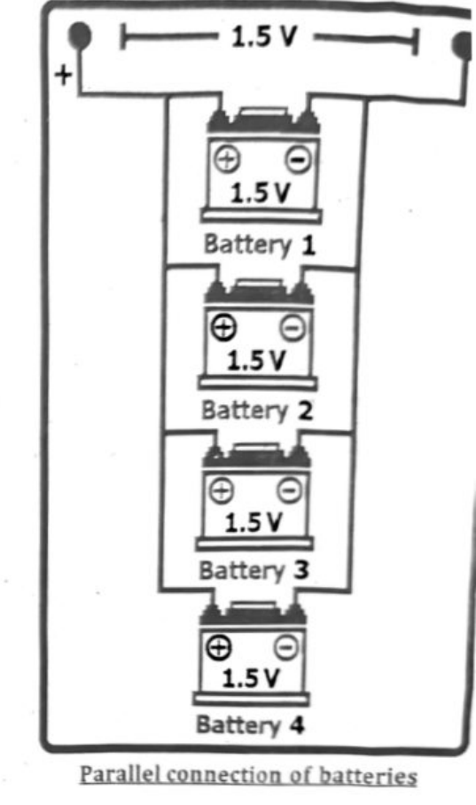
When identical sources (like batteries or voltage sources) are connected in parallel, the total electromotive force (e.m.f) of the combination is equal to the (e.m.f) of a single source. This is because in a parallel circuit, the voltage across all components is the same, and since the sources are identical, they all have the same (e.m.f) When identical sources (like batteries with the same voltage) are connected in parallel, the total (e.m.f) (electromotive force) is the same as one battery.
Example:
If you connect three 1.5 V batteries in parallel, the total e.m.f. is still:
Total e.m.f = 1.5 V
Series Combination of e.m.f Sources:
When positive terminal of an (e.m.f) source, like battery, is connected to negative terminal of another source and so on. Finally the negative terminal of the first (e.m.f) source is connected to the positive terminal of the last source through other circuit elements like bulbs, fans etc. as shown in figure.
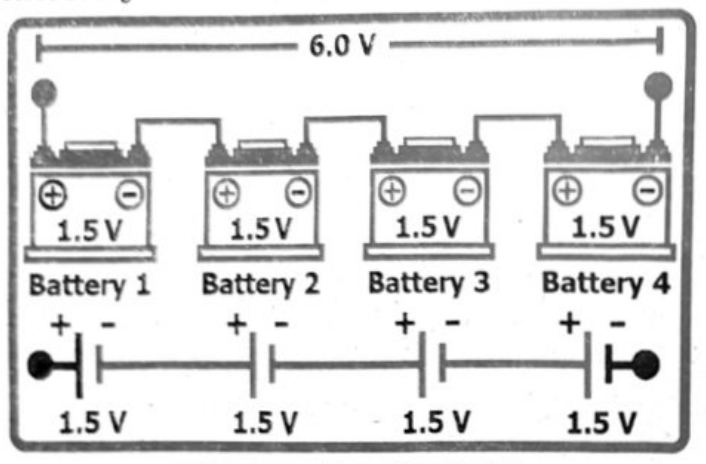
Parallel Combination of e.m.f Sources:
In parallel combination of (e.m.f) sources, the positive and negative terminals of all the sources are connected to each other respectively. Finally, the load is connected by taking one connection from positive terminal and one from negative terminal as shown in figure below.
- When identical sources (like 12 V in given figure) are connected in parallel, the equivalent (e.m.f) is equal to the (e.m.f) of one of the sources i.e., 12 V here.
- Generally, for ‘n’ number of batteries connected, we can mathematically write:
$$\varepsilon_{\text{net}} = \varepsilon_1 + \varepsilon_2 + \varepsilon_3 + \cdots + \varepsilon_n$$ (i) - Parallel combination of (e.m.f) sources is used when a higher ampere-hour is required as compared to the available sources and no change in voltage values. If, for example, the above batteries are
equivalent rating when connected in parallel will be 12
When batteries are connected in series, their voltages add up. If one battery is weaker, it can cause issues. The weaker battery can limit the power of the entire system and reduce its overall performance. It might also get overworked, leading to overheating or damage. Balancing batteries in series is important for safe and steady power delivery. To keep them balanced, we can use special circuits that monitor and control their charge, or occasionally charge each battery individually. Proper balancing ensures the system works efficiently and safely.
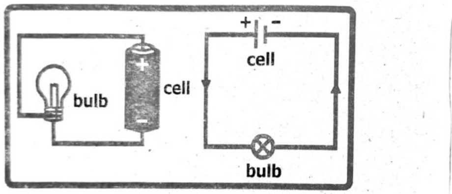
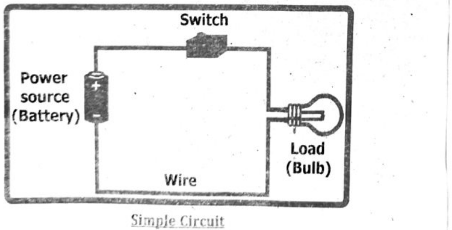
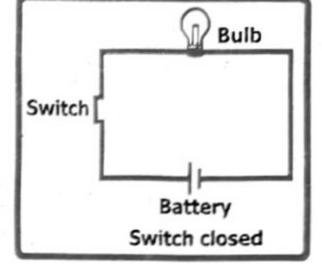
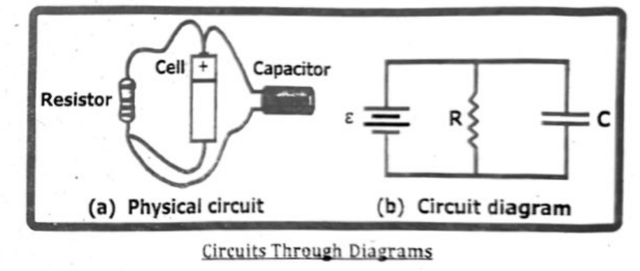
A simple circuit diagram with a cell (battery), a switch, and a bulb can be drawn by representing the cell as two parallel lines (longer for positive, shorter for negative), the switch as a break in a line (closed with a bridge for closed switch), and the bulb as a circle with a filament symbol.
SCIENCE TIDBITS
Electricity loves to travel in closed loops called circuits! Imagine it like a race track for electrons—these tiny particles zoom around the circuit but must start and end at the same point. If there's a break in the track (an open circuit), the electrons come to a halt, and nothing happens. But if the path is complete, they speed along, powering lights, gadgets, and so much more!
Circuit Symbols:
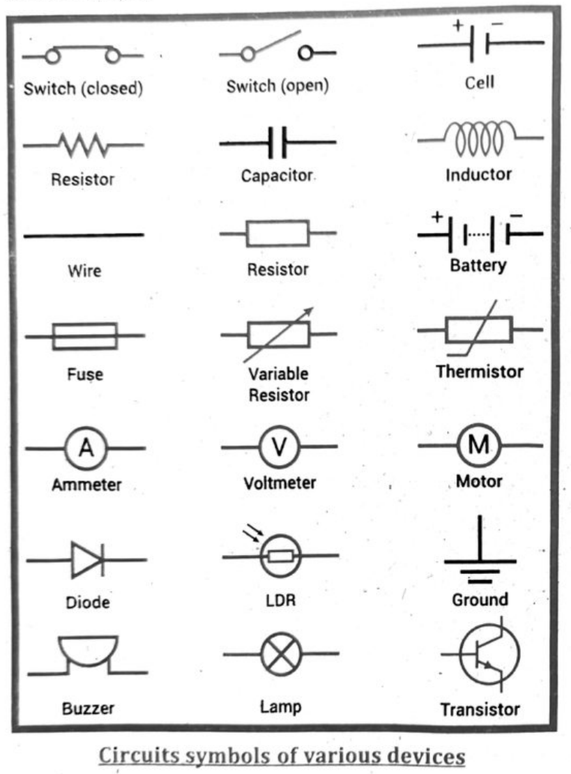
Specifically:
- the current at every point in a series circuit is the same
- the sum of the currents entering a junction in a parallel circuit is equal to the sum of the currents that leave the junction
- the total p.d. across the components in a series circuit is equal to the sum of the individual p.d.s across each component
- the p.d. across an arrangement of parallel resistances is the same as the p.d. across one branch in the arrangement of the parallel resistances
In a series circuit, the current is the same at every point, while the total voltage is the sum of individual voltage drops across each component. Conversely, in a parallel circuit, the voltage across each branch is the same, and the total current entering a junction equals the total current leaving it.
Series Circuits:
Current is the same:
The current flowing through each component in a series circuit is identical. This is because there's only one path for the current to flow.
Total voltage is the sum of individual voltages:
The total voltage across a series circuit is the sum of the voltage drops across each individual component. For example, if you have a battery with a certain voltage and multiple resistors in series, the voltage drop across each resistor will add up to the battery's voltage.
Parallel Circuits:
Current division at junctions:
In a parallel circuit, the current splits at junctions. The sum of the currents entering a junction must equal the sum of the currents leaving that junction. This is a consequence of the conservation of charge.
Voltage is the same across parallel branches:
The voltage across each branch of a parallel circuit is the same. It’s equal to the voltage of the power source or the voltage across the parallel arrangement.
To solve circuit problems involving current and voltage, we use these fundamental rules:
Ohm’s Law states:
$$V = IR \quad (\text{Voltage = Current} \times \text{Resistance})$$
Kirchhoff’s Current Law (KCL) states the total current entering a node equals the total current leaving, and Kirchhoff’s Voltage Law (KVL) states the sum of voltage drops around a loop equals the source voltage.
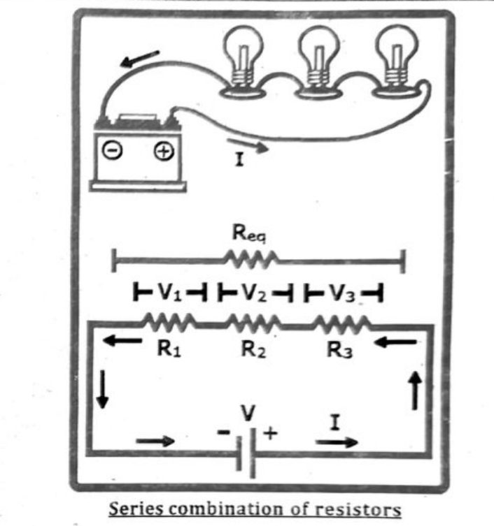
The overall resistance of the collection of resistors is equal to the sum of the individual resistance values.
$$R_e = R_1 + R_2 + R_3$$
If resistances $R_1 + R_2 + R_3 + \cdots + R_n$ are connected in series, then the equivalent resistance of the combination will be given by:
$$R_e = R_1 + R_2 + R_3 + \cdots + R_n$$
In series combination of resistors equivalent resistance is greater than any of the individual resistance of the combination.
For example, if you have a 10 ohm resistor and a 20 ohm resistor connected in series, the combined resistance would be:
10 ohms + 20 ohms = 30 ohms
When two resistors are connected in parallel, the current has multiple paths to flow, which effectively lowers the total resistance of the circuit.
The reciprocal of equivalent resistance $\frac{1}{R_e}$ of the combination is the sum of the reciprocals of the individual resistances.
$$\frac{1}{R_e} = \frac{1}{R_1} + \frac{1}{R_2} + \frac{1}{R_3}$$
If resistances $R_1, R_2, R_3, \ldots, R_n$ are connected in parallel then the equivalent resistance of the combination will be given by: $$\frac{1}{R_e} = \frac{1}{R_1} + \frac{1}{R_2} + \frac{1}{R_3} + \cdots + \frac{1}{R_n}$$
In parallel combination of resistors equivalent resistance is smaller than any of the individual resistance of the combination.
To calculate current, voltage, and resistance in a circuit, Ohm’s Law ($V = IR$) is used. You can apply it to the entire circuit or to individual components. If you know two values, you can calculate the third. For series circuits, total resistance is the sum of individual resistances, and current is the same throughout. For parallel circuits, voltage is the same across all branches, and total resistance can be calculated using conductance.
Ohm’s Law:
- $V = I \times R$: (Voltage = Current × Resistance)
- $I = V / R$: (Current = Voltage / Resistance)
- $R = V / I$: (Resistance = Voltage / Current)
Series Circuits:
- Total Resistance: $R_{\text{total}} = R_1 + R_2 + R_3 + \cdots$
- Current: The same current flows through all components.
Parallel Circuits:
- Voltage: The same voltage exists across all branches.
- Total Resistance: Can be calculated using:
$$\frac{1}{R_e} = \frac{1}{R_1} + \frac{1}{R_2} + \frac{1}{R_3} + \cdots + \frac{1}{R_n}$$
Example:
Let’s say you have a simple circuit with a 12 V battery and a 6 Ω resistor.
- To find the current ($I$), you would use $I = V / R$. So, $I = 12\text{ V} / 6\text{ Ω} = 2\text{ A}$.
- If you had a second 6 Ω resistor in series, the total resistance would be 12 Ω (6 Ω + 6 Ω). The current would then be 12 V / 12 Ω = 1 A.
- If those same two 6 Ω resistors were in parallel, the total resistance would be 3 Ω (using the conductance formula). The current would then be 12 V / 3 Ω = 4 A, but this current would be split between the two branches.
Parallel Combination of Resistors:
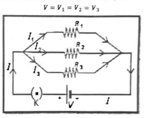
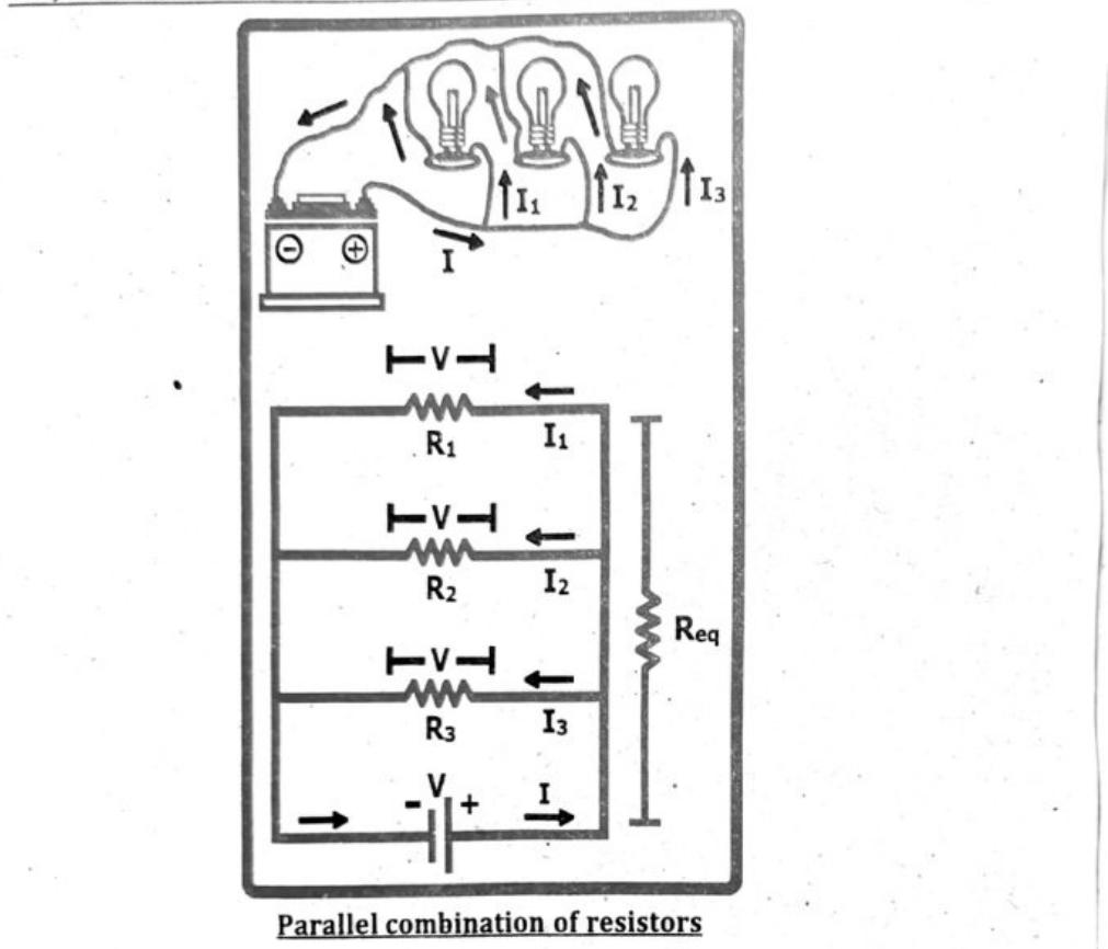
- In parallel combination one end of each resistor is connected with positive terminal of battery while the other end of each resistor is connected with the negative terminal of battery. Therefore, the voltage is same across each resistor which is equal to the voltage of the battery, i.e. $$V = V_1 = V_2 = V_3$$
- In parallel circuit, the total current equals the sum of the currents in various resistances i.e., $$I = I_1 + I_2 + I_3$$
- The reciprocal of equivalent resistance $\frac{1}{R_e}$ of the combination is the sum of the reciprocals of the individual resistances.
$$\frac{1}{R_e} = \frac{1}{R_1} + \frac{1}{R_2} + \frac{1}{R_3}$$If resistances $R_1, R_2, R_3, \ldots, R_n$ are connected in parallel then the equivalent resistance of the combination will be given by:
$$\frac{1}{R_e} = \frac{1}{R_1} + \frac{1}{R_2} + \frac{1}{R_3} + \cdots + \frac{1}{R_n}$$
In parallel combination of resistors equivalent resistance is smaller than any of the individual resistance of the combination.
NTC thermistors and light-dependent resistors (LDRs) are both variable resistors, but they react to different environmental factors. NTC thermistors decrease in resistance as temperature increases, making them useful for temperature sensing. LDRs, on the other hand, decrease in resistance as light intensity increases, making them suitable for light sensing applications. Both types of sensors can be used in potential dividers to create voltage outputs that change with the measured environmental variable, allowing them to be used in a wide range of control systems.
NTC Thermistors:
- Action: NTC thermistors are made of semiconducting materials that exhibit a negative temperature coefficient of resistance. This means their resistance decreases as their temperature rises.
- Use as Input Sensors: They can be used to detect changes in temperature, such as in fire alarms, temperature controllers, or to limit inrush currents in power supplies.
- Circuit Example: In a potential divider circuit, an NTC thermistor’s resistance change will cause a corresponding change in voltage output, which can be used to trigger actions in a circuit.
Light-Dependent Resistors (LDRs):
- Action: LDRs are also known as photoresistors. Their resistance decreases as the amount of light falling on them increases.
- Use as Input Sensors: LDRs can be used to detect changes in light levels, for example, in automatic streetlights or burglar detectors.
- Circuit Example: Similar to NTC thermistors, LDRs can be part of a potential divider, where a change in resistance due to light intensity alters the output voltage, which can then be used to control a connected device.
In essence, both NTC thermistors and LDRs are utilized as input sensors because their resistance changes in a predictable way based on their respective environmental factors (temperature or light). This change in resistance is then translated into a voltage change in a circuit, providing a usable signal for control systems.
A variable potential divider, also known as a potentiometer or rheostat, uses two resistors in series to create a variable output voltage. By adjusting the position of a sliding contact (wiper) along the resistance element, the ratio of the resistance between the wiper and the two ends of the divider changes, thus altering the output voltage. This allows for precise control of voltage levels within a circuit.
How it works:
- Series Connection: The two resistors are connected in series across a voltage source.
- Voltage Division: The input voltage is divided across the two resistors based on their resistance values.
- Adjustable Output: A wiper (sliding contact) moves along the resistance element, effectively changing the ratio of resistance between the wiper and each end of the divider.
- Variable Voltage: As the resistance ratio changes, the voltage at the wiper (output voltage) also changes, allowing for a variable voltage output.
Resistors as Potential Dividers:
Extended Tier Only:
When two resistors are connected in series, the power source's e.m.f. is split between the resistors.
This potential difference splits in the same ratio as the resistance of the two resistors.
The ratio of potential differences across each resistor can be found using the following equation:
$$\frac{R_1}{R_2} = \frac{V_1}{V_2}$$
Where:
- $R_1$ is the resistance of resistor 1 in ohms, Ω
- $R_2$ is the resistance of resistor 2 in ohms, Ω
- $V_1$ is the potential difference across resistor 1 in volts, V
- $V_2$ is the potential difference across resistor 2 in volts, V
The equation for a potential divider circuit with two resistors, $R_1$ and $R_2$, where $R_1$ is across $V_1$ and $R_2$ is across $V_2$, is indeed $R_1 / R_2 = V_1 / V_2$. This equation highlights that the ratio of the resistances is equal to the ratio of the corresponding voltage drops across them.
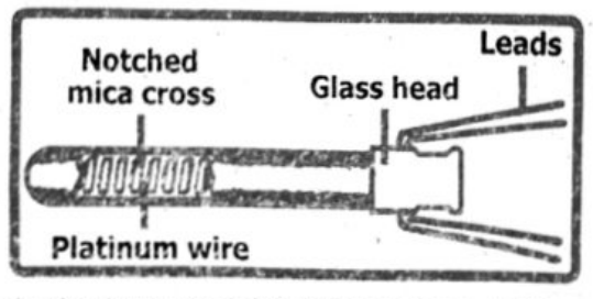
Resistance thermometers, also called Resistance Temperature Detectors (RTDs), are sensors used to measure temperature by correlating the resistance of the RTD element with temperature. Most RTD elements consist of a length of fine coiled wire, wrapped around a ceramic or glass core. The RTD element is made from a pure material such as Platinum, Nickel, Copper that has a predictable change in resistance as the temperature changes; it is this predictable change that is used to determine temperature.
Platinum is the best metal for RTDs because it follows a very linear resistance-temperature relationship and it follows the R vs T relationship in a highly repeatable manner over a wide temperature range. The unique properties of platinum make it the material of choice for temperature standards with the range from −185°C to 630°C.
NON-LINEAR RESISTORS:
In non-linear resistors the resistance value fluctuates in response to temperature, light, or voltage. These resistors are further divided as thermistors, varistors and photo resistors.
(i) Thermistor:
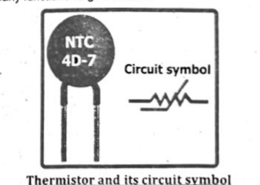
A thermistor is a type of resistor whose resistance varies significantly with temperature. Thermistor is short for thermal-resistor, device which have heat sensitive resistance, thus the temperature coefficient of thermistor is very high. The material used in a thermistor is generally a semiconductor ceramic or polymer.
Thermistors are of two types:
- Positive Temperature Coefficient (PTC): thermistors increases its resistance with the increase of temperature and
- Negative Temperature Coefficient (NTC): thermistors decreases its resistance with the increase of temperature.
Thermistors of different sizes and shapes are formed according to the need of the industry. Their sensitivity to change in temperature enables them to perform many functions as given below.
- Inrush current limiter: An inrush current limiter or input surge current, is the peak current drawn by an electrical device when powered on. For example, incandescent bulbs have high inrush currents until their filaments heat up. NTC thermistors can limit inrush current in power supply circuits by initially exhibiting high resistance, which restricts large currents during startup.
- Overheating Alarm: NTC thermistors can trigger alarms when the temperature of motor, transformer, or generator windings rises. They maintain high resistance at lower temperatures, allowing minimal current flow. As temperature increases, resistance drops, allowing more current to
C. Temperature Measurement: Thermistors provide precise temperature measurements due to their high temperature coefficient. Their resistance changes with temperature, enabling effective detection and response to temperature variations.
(ii) Varisters (VDR):
Varisters are voltage dependent Resistors (VDR) which are used to eliminate the high voltage transients. They are type of variable resistors used to protect circuits from destructive voltage spikes. When voltage increases (due to lighting or line faults) across a connected sensitive device or system, then it reduces the level of voltage to a secure level i. e. it changes the level of voltages. Varistors are typically made from metal oxide materials, with zinc oxide (ZnO) being the most common. They consist of a ceramic body composed of zinc oxide grains, which are interspersed with other metal oxides such as bismuth, cobalt, and manganese. The grain boundaries act as the non-linear junctions that give the varistor its voltage-dependent characteristics.
(iii) Light Dependent Resistor (LDR):
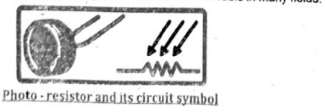
Light Dependent Resistor (LDR), also known as Photo Resistor or photocell, is a light-sensitive device that changes resistance based on the intensity of light. In low light conditions, LDRs have high resistance, which decreases as light intensity increases. They are commonly used in light-sensing applications, with materials like cadmium sulfide and lead sulfide used to make them. The surface of the LDR is designed to be exposed to light, with a serpentine pattern to increase light exposure. LDRs sense light levels and adjust resistance accordingly, making them useful in various applications like automatic lighting control, photography, and security systems. Light Dependent Resistors (LDRs) are versatile and cost-effective components used to detect and respond to changes in light levels. Their simplicity and wide range of applications make them valuable in many fields.

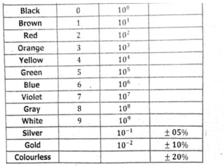
Resistor color codes are used to quickly identify the resistance value and tolerance of a resistor, particularly on smaller components where printed numbers are impractical. This system allows for easy identification without needing to read tiny text, making it efficient for both manufacturing and troubleshooting.
Justification:
Space Efficiency:
Resistors, especially those used in compact electronic devices, are often too small to have their resistance value printed legibly. Color bands offer a compact and space-saving way to encode this information.
Ease of Identification:
Color codes allow for rapid visual identification of resistance values, crucial for assembly lines and repair work.
Standardization:
Resistor color codes are standardized by organizations like the International Electrotechnical Commission (IEC), ensuring consistency and reducing confusion.
Tolerance Indication:
In addition to the resistance value, color codes also indicate the tolerance, which is the acceptable range of variation in the resistance.
Illustrative Example:
A four-band resistor is the most common type. Here's how it works:
- First Band: Represents the first digit of the resistance value.
- Second Band: Represents the second digit of the resistance value.
- Third Band (Multiplier): Indicates the power of ten by which the first two digits are multiplied.
- Fourth Band (Tolerance): Shows the acceptable percentage variation in the resistance value.
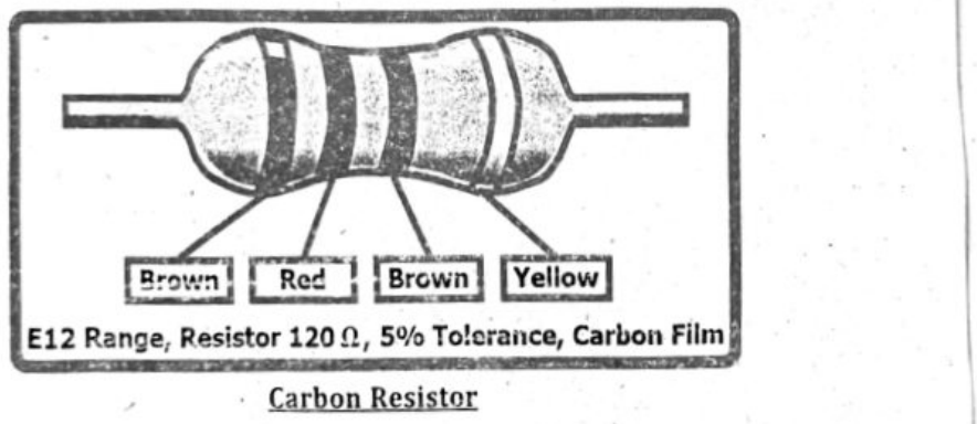
For example, a resistor with bands:
- Brown (1): First digit is 1.
- Black (0): Second digit is 0.
- Red (× 100): Multiply by 100.
- Gold (± 5%): Tolerance of ± 5%.
This translates to a resistance value of $10 \times 100 = 1000$ ohms (1kΩ) with a tolerance of ± 5%. This means the actual resistance could be anywhere between 950 Ω and 1050 Ω.
The visible resistor colour-code table lists:
| Black | 0 | $10^0$ | |
| Brown | 1 | $10^1$ | |
| Red | 2 | $10^2$ | |
| Orange | 3 | $10^3$ | |
| Yellow | 4 | $10^4$ | |
| Green | 5 | $10^5$ | |
| Blue | 6 | $10^6$ | |
| Violet | 7 | $10^7$ | |
| Gray | 8 | $10^8$ | |
| White | 9 | $10^9$ | |
| Silver | $10^{-1}$ | ± 05% | |
| Gold | $10^{-2}$ | ± 10% | |
| Colourless | ± 20% |
The illustrated resistor is labeled with bands Brown, Red, Brown, Yellow. Its caption states: “E12 Range, Resistor 120 Ω, 5% Tolerance, Carbon Film.”
Electricity has numerous applications in modern life. Common uses include heating (e.g., electric heaters, ovens, boilers), lighting (e.g., streetlights, household lights), battery charging (e.g., for phones, laptops), and powering motors (e.g., in washing machines, dryers, and many industrial machines). It also powers electronic systems like TVs, computers, and gaming consoles.
- Heating: Electricity is used for various heating purposes, including space heating (electric heaters, heat pumps), cooking (ovens, stovetops), and water heating (electric water heaters).
- Lighting: From simple light bulbs to complex lighting systems in buildings and public spaces, electricity is essential for illumination.
- Battery Charging: Many portable devices rely on rechargeable batteries that are charged using electricity, such as mobile phones, laptops, tablets, and electric vehicles.
- Powering Motors: Electricity drives a vast array of motors in various applications, from household appliances like washing machines and refrigerators to industrial machinery and electric vehicles.
- Electronic Systems: Electricity is the lifeblood of countless electronic devices, including computers, televisions, gaming consoles, and communication systems.
- Industrial Processes: Many industrial processes, such as manufacturing, refining, and metalworking, rely on electricity for powering machinery and other equipment.
- Transportation: Electric vehicles (cars, buses, trains, etc.) and electric public transportation systems rely on electricity to move people and goods.
- Commercial and Residential Use: Electricity powers a wide range of devices and systems in commercial buildings (offices, stores) and homes, including lighting, heating, cooling, appliances & communication systems.
- Backup and Emergency Power: Electrical systems like generators and battery backups ensure continuity of power during outages.
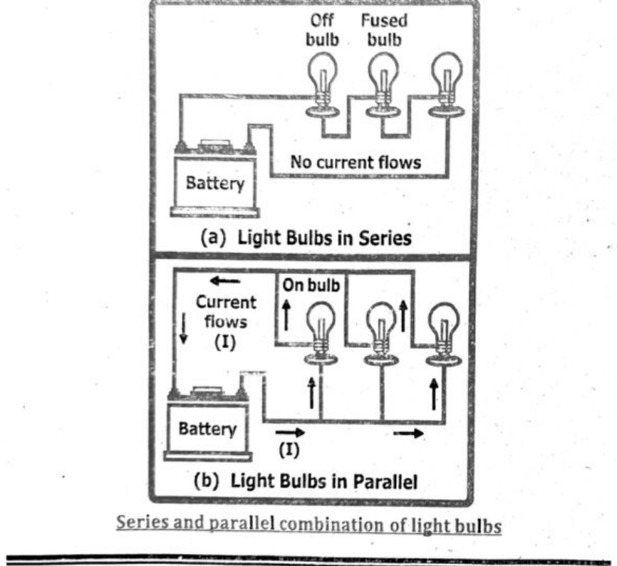
Connecting lamps in parallel in a lighting circuit offers several advantages. Primarily, if one lamp fails (blows), the others will continue to operate, unlike in a series circuit where a single failure would break the circuit and extinguish all lamps. Additionally, in a parallel circuit, each lamp receives the full voltage of the power source, ensuring consistent brightness, whereas in a series circuit, the voltage is divided among the lamps.
- In parallel combination of resistors equivalent resistance is smaller than any of the individual resistance of the combination.
Detailed breakdown:
- Independent Operation: Each lamp functions independently, meaning a problem with one lamp doesn’t affect the others. This is crucial for maintaining functionality in a lighting system.
$$P = I \times V$$
Where:
- $P$ = Power (in watts, W)
- $I$ = Current (in amperes, A)
- $V$ = Voltage (in volts, V)
Problem 1:
A device uses 3 A of current at 12 V.
$$P = I \times V = 3 \times 12 = 36\ W$$
Problem 2:
A fan runs on 0.5 A at 220 V.
$$P = I \times V = 0.5 \times 220 = 110\ W$$
The formula $E = IVt$ calculates the energy ($E$) transferred in a circuit by multiplying the current ($I$), voltage ($V$), and time ($t$). This equation can be used to solve various problems involving electrical energy transfer.
Problem 1:
A 2 A current flows through a 6 V device for 10 seconds.
$$E = IVt = 2 \times 6 \times 10 = 120\ J$$
Problem 2:
A phone charger uses 0.5 A at 5 V for 60 seconds.
$$E = IVt = 0.5 \times 5 \times 60 = 150\ J$$
Energy Dissipation in a Resistance:
When current flows through a resistor, some of the electrical energy delivered to the resistor is converted into heat energy and it is dissipated. This heating effect of current is known as Joule’s heating effect. Joule’s law is a mathematical description of the rate at which resistance in a circuit converts electric energy into heat energy.
We refer to the conversion of potential energy into heat as dissipation.
Joule’s Law:
The amount of heat generated in a resistance due to flow of charges is equal to the product of square of current $i$, resistance $R$ and the time duration $t$.
Mathematical form of Joule’s Law:
Consider two points with a potential difference of $V$ volts. Hence, when $Q$ coulomb of charge flows between these two points, then we will get $QV$ joule of energy.
Electrical energy supplied by $Q$ charge $W = QV$ joule (i)
Now current, when charges $Q$ flow in time $t$, is defined as:
$$I = \frac{Q}{t} \qquad\text{or}\qquad Q = It$$
Put in equation (i) we get:
$$W = V \times I \times t$$
From Ohm’s law, we have $V = IR$.
So, the energy supplied by $Q$ charge is:
$$W = (IR) \times I \times t = I^2Rt$$
$$\Rightarrow\quad W = \left(\frac{V}{R}\right)^2 \times R \times t \quad\Rightarrow\quad W = \frac{V^2}{R^2} \times R \times t \quad\Rightarrow\quad W = \frac{V^2t}{R}$$
This equation is called Joule’s law.
Using the equation $E = qV$, where $q$ is in coulombs (C) and $V$ is in volts (V), and since $1\,\mathrm{V} = 1\,\mathrm{J}/1\,\mathrm{C}$, we get:
$$E = q \times V = C \times \frac{J}{C} = J$$
So, the unit of electrical energy $E$ is joule (J).
Kilowatt-hour (kWh) is defined as the amount of energy consumed by a device operating at a power of one kilowatt (1 kW) for a duration of one hour (1 h).
Equation:
$$\text{Energy (kWh)} = \text{Power (kW)} \times \text{Time (h)}$$
A kilowatt-hour (kWh) is a unit of energy, specifically representing the amount of energy used when a 1,000 watt (1 kilowatt) appliance runs for one hour. It’s a common way to measure electricity consumption, particularly on energy bills. For example, if a 100 watt light bulb is left on for 10 hours, it will consume 1 kWh of energy.
Choosing components with suitable power ratings is crucial to ensure safe and reliable operation of electronic circuits. Exceeding a component’s power
Conversely, using components with excessive power ratings can lead to higher costs and larger sizes than necessary.
To calculate the cost of using electrical appliances, you need to determine the energy consumption in kilowatt-hours (kWh) and then multiply that by the cost per kWh. The energy consumption is calculated by multiplying the appliance’s wattage by the time it’s used (in hours) and then dividing by 1000. The formula is: (Wattage × Hours Used) / 1000 = kWh. Then, multiply the kWh by the cost per kWh to find the total cost.
To calculate the cost of using electrical appliances where energy unit is kWh. We calculate the cost of using electrical appliances where energy unit is kWh.
$$\text{Energy (kWh)} = \text{Power (kW)} \times \text{Time (hours)}$$
$$\text{Cost} = \text{Energy (kWh)} \times \text{Rate (PKR / kWh)}$$
Given:
Power = 2 kW; Time = 3 hours
Calculate energy used:
$$\text{Energy} = 2 \times 3 = 6\,\text{kWh}$$
Calculate cost:
$$\text{Cost} = 6 \times 10 = \text{Rs. }60$$
The cost of using the heater for 3 hours is Rs. 60.
The unit kilowatt-hour (kWh) measures electrical energy, not electric power. While kW (kilowatt) measures power, kWh measures the amount of energy used over time. One kWh represents the amount of energy consumed by a 1 kilowatt device operating for one hour.
Mathematically,
$$1\,\text{kW-hr} = 1000\,\text{W} \times 1\,\text{hr}$$
$$= 1000\,\text{J/s} \times 3600\,\text{s} = 3.6 \times 10^6\,\text{J}$$
One kilowatt-hour represents the amount of energy consumed when a power of one kilowatt is used for one hour.
$$\text{Energy (kWh)} = \text{Power (kW)} \times \text{Time (hours)}$$
$$\text{Cost} = \text{Energy (kWh)} \times \text{Rate (PKR / kWh)}$$
For example, if a device rated at 500 watts (0.5 kW) operates for 2 hours, it will consume 1 kWh of energy ($0.5\text{ kW} \times 2\text{ hours} = 1\text{ kWh}$).
Putting values, $E = 2.2\text{ kW} \times 720\text{ h}$.
Therefore, $E = 1584\text{ kWh}$.
The total consumed energy is 1584 kWh (or 1584 commercial units). The cost can be calculated as:
$$\text{Cost} = E \times \text{Tariff Rate} = (1584\text{ kWh}) \times (\text{PKR }25.0)$$
$$\text{Cost} = 39{,}600\text{ rupees}$$
The cost of electricity for an AC for the whole month is PKR 39,600.
All of the options (a), (b), (c), and (d)—damaged insulation, overheating cables, damp conditions, and excess current from overloading—are common electrical hazards that can be caused by malpractice and lack of maintenance; improper care or neglecting regular inspections can lead to these dangerous situations.
Explanation:
Damaged insulation:
When the protective coating around electrical wires deteriorates due to wear, exposure to moisture, or other factors, it can expose live wires, increasing the risk of electric shock.
Overheating cables:
If too much current flows through a cable, it can overheat, potentially causing the cable to melt, ignite a fire, or damage surrounding materials.
Damp conditions:
Moisture near electrical equipment can create a pathway for electricity to flow, leading to short circuits, electrical shocks, or fires.
Excess current from overloading:
Plugging too many devices into a single outlet or extension cord can cause an overload, resulting in overheating, potential fires, and damage to the circuit.
Trip switches (circuit breakers) and fuses are both safety devices that protect electrical circuits from overcurrents. Fuses meet and break the circuit when the current exceeds a certain level, while trip switches (circuit breakers) automatically open the circuit when an overlead is detected. Choosing the correct fuse rating or trip switch setting is crucial for effective protection. The rating should be slightly higher than the expected current of the circuit to avoid nuisance tripping or blowing, but not so high that it allows dangerous overcurrents to pass through.
Fuses:
How they work:
Fuses contain a thin wire that melts and breaks the circuit when the current exceeds its rating.
Use:
Fuses are used in plugs and fuse boxes to protect individual appliances or circuits.
Choosing the right fuse:
- Calculate the current required by the appliance using the formula:
$$\text{Current (Amps)} = \frac{\text{Power (Watts)}}{\text{Voltage (Volts)}}$$ - Select the fuse with the next higher rating than the calculated current. For example, if an appliance needs 3.1 amps, a 5 amp fuse is appropriate.
- Common fuse ratings include 3 A, 5 A, and 13 A.
After a fuse blows:
The fuse needs to be replaced with a new one of the same rating.
Trip Switches (Circuit Breakers):
How they work:
Trip switches (also known as circuit breakers) use a mechanism to detect overcurrents and automatically open the circuit. Some trip switches also protect against earth leakage.
Use:
Trip switches are typically found in consumer units (fuse boxes) and protect entire circuits or groups of circuits.
Choosing the right trip switch:
- Determine the maximum current that the circuit (including wiring) can handle.
- Select a trip switch with a rating slightly higher than the circuit’s maximum current capacity.
- For example, if a circuit can handle 16 amps, a 20 amp trip switch might be appropriate.
After a trip:
The trip switch can usually be reset after the fault is identified and rectified.
When a live wire touches a metal case that is earthed, a large current flows through the earth wire to the ground. This creates a short circuit, and the fuse blows or the circuit breaker trips, cutting off the electricity. This prevents the metal case from staying live and protects the user from electric shock.
RESIDUAL CURRENT DEVICES:
Ground fault circuit interrupters (GFCIs) are crucial safety devices that protect against electrical shock by rapidly interrupting the flow of electricity when a ground fault is detected. They work by comparing the current flowing into a circuit to the current returning from it, and if there’s a difference (indicating a leakage current, or ground fault), the GFCI trips, cutting off the power in milliseconds. This rapid response helps prevent severe injuries from electrical shock, especially in areas prone to moisture.
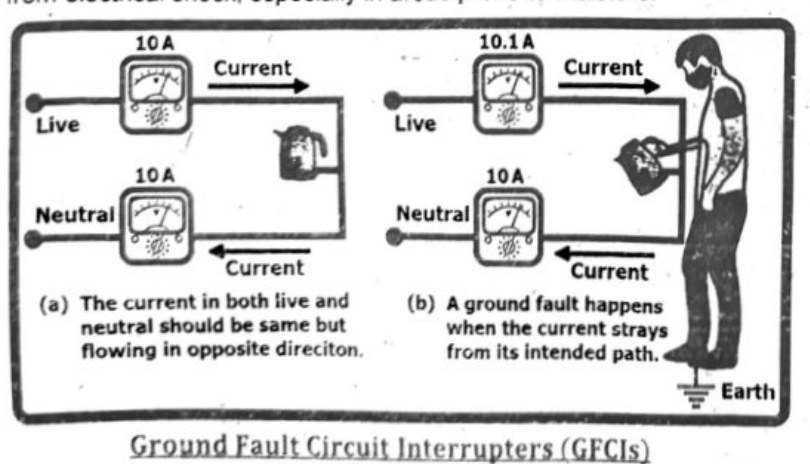
Electrical appliances with metal casings need to be either double-insulated or earthed to prevent electric shock. If a live wire inside the appliance comes loose and touches the metal casing, it can become energized. Without a safety mechanism, anyone touching the energized casing could receive a dangerous electric shock.
Double Insulation:
- Double insulation provides two layers of insulation between live parts and the user.
- This eliminates the need for an earth connection because there’s no possibility of the casing becoming live, even if one layer of insulation fails.
Earthing:
- Earthing provides a low-resistance path for fault current to flow to the ground.
- If a live wire touches the earthed casing, the high current will cause the fuse to blow, cutting off the power supply and preventing electrocution.
- This works because the earth wire is connected to a grounding point (like the earth itself) and provides a safe route for the current to flow away from the appliance.
In essence, both double insulation and earthing serve to prevent the appliance casing from becoming energized and causing an electrical shock.
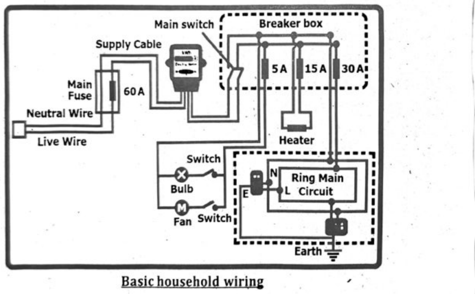
A mains circuit consists of three wires: a live wire (also called line wire), a neutral wire, and an earth wire. The live wire carries current to the appliance, the neutral wire carries current back, and the earth wire is a safety wire that prevents electric shock in case of a fault.
A standard mains electrical circuit includes three wires: a live wire (also known as the line wire), a neutral wire, and an earth wire. These wires each have a specific function within the circuit, with the live wire carrying electricity to the appliance, the neutral wire completing the circuit, and the earth wire providing a safety mechanism.
- A mains circuit consists of a live wire (line wire) which carries electricity to the appliance, a neutral wire which carries it away from the appliance and an earth wire. Because the live wire carries electricity to the appliance, a switch must be connected here to switch the circuit off safely in case there is a fault with it.
- Without the earth wire, if a fault occurs and the live wire becomes loose, there is a danger that it will touch the case. The next person who uses the appliance could get electrocuted.
- The earth wire is therefore connected to the case and is attached to a metal plate or water pipe underground. As the wire is made of copper, the earth wire provides a low resistance path to the ground. In the event of a fault, the live current passing through the case will follow this path to the ground instead of passing through a person.
CIRCUIT BREAKERS:
Circuit breakers are crucial in electrical circuits as they protect against overcurrents, preventing damage to equipment and reducing the risk of electrical fires and shocks. They automatically interrupt the flow of electricity in the event of a short circuit or overload, acting as a safety mechanism. Unlike fuses, which need replacement after a trip, circuit breakers can be reset, allowing for convenient and repeated use. Circuit breakers are connected to the live wire in a circuit to ensure that when the breaker is switched off, the entire circuit downstream of the breaker is de-energized, minimizing the risk of electric shock. If the breaker were connected to the neutral wire, the appliance or equipment could still be live, as the neutral wire simply provides the return path for the current and doesn't interrupt the flow of electricity at the source.
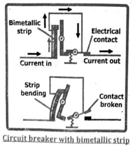
Fuses and circuit breakers are connected to the live wire to ensure safety. When a fault occurs, like a short circuit, the excessive current will flow through the live wire and be interrupted by the fuse or circuit breaker before it can reach the appliance or user, thus preventing electrical shocks and fires.
Domestic appliances are connected in parallel in electrical circuits to ensure that each appliance receives the full voltage from the power source and can operate independently of other appliances. If one appliance fails or is turned off, it doesn't affect the operation of the others. This parallel connection also allows for increased current capacity and makes it easier to add or remove appliances from the circuit.
Detailed explanation:
Independent Operation: In a parallel circuit, each appliance has its own path for current flow. This means that if one appliance is turned off, the others continue to receive power and operate normally.
Equal Voltage: Each appliance in a parallel circuit receives the full voltage of the power source (e.g., 220 V in many countries). This ensures that all appliances operate at their intended voltage and power levels.
Increased Current Capacity: When multiple appliances are connected in parallel, the total current draw is shared among them. This allows for a higher total current capacity for the circuit without overloading any single appliance.
Ease of Adding or Removing Appliances: Because each appliance has its own path, it's easy to add or remove appliances from a parallel circuit without affecting the others.
Safety: If a fault occurs in one appliance, the parallel connection helps prevent the entire circuit from shutting down, potentially improving safety.
Household Wiring System:
A mains circuit is composed of three wires: a live wire (line wire), a neutral wire, and an earth wire as shown in figure. Each wire has a distinct function in guaranteeing the secure distribution and utilization of electricity. It is crucial to comprehend their roles in order to uphold electrical safety in residential and industrial environments.
- The live wire, also known as the line wire, is responsible for carrying the electrical current from the power source to the electrical devices or appliances. The live wire carries the potential difference or voltage that powers the electrical devices.
- The neutral wire, on the other hand, is responsible for completing the electrical circuit. It provides a return path for the electrical current back to the power source. It carries the same current as the live wire but with an opposite polarity. The earth wire, also known as the grounding wire, is a safety measure in case of electrical faults or malfunctions.
- The earth wire provides a low-resistance path for the electrical current to flow into the ground, preventing electric shocks and reducing the risk of fire. It acts as a safety backup, redirecting the current away from people or objects in case of a fault.
Electric shock can cause a range of severe injuries, primarily due to the passage of electrical current through the body. These injuries can include burns, cardio respiratory failure, and seizures. The severity of the damage depends on factors like the voltage, current, type of current (AC or DC), duration of exposure, and the individual’s health.
Burns:
External Burns: Electrical current flowing through the body can cause burns at the entry and exit points of the current, as well as along its path. These can range from superficial skin burns to deep tissue damage.
Internal Burns: Even if external burns are minimal, internal tissues and organs can be severely damaged by the heat generated by the electrical current.
Cardio Respiratory Failure:
Heart Problems: Electrical shock can disrupt the heart’s electrical system, leading to arrhythmias (irregular heartbeat), ventricular fibrillation (a chaotic heart rhythm), or cardiac arrest (heart stopping).
Respiratory Issues: The current can affect the nerves that control breathing, leading to respiratory arrest (breathing stops) or breathing difficulties.
Seizures:
Nervous System Disruption: Electrical shock can disrupt the normal electrical activity in the brain, causing seizures.
Muscle Spasms: The current can also cause involuntary muscle contractions (spasms), which may be strong enough to cause falls and injuries.
Long-term Effects: Even after the initial shock, individuals may experience long-term effects such as nerve damage, chronic pain, cognitive problems, and psychological trauma.
| Sr No. | Current in milliamperes (mA) | Effect on body |
|---|---|---|
| 1. | 2 to 3 | A slight tingling sensation |
| 2. | 9 to 10 | Moderately painful |
| 3. | 10 to 20 | Highly painful |
| 4. | 20 to 30 | A person to seize the line and be unable to let go of the circuit. |
| 5. | 30 to 40 | Causing muscular paralysis |
| 6. | 40 to 60 | Causing breathing difficulty |
| 7. | 60 to 100 | Breathing becomes extremely difficult |
| 8. | 100 to 200 | Generally cause death because the heart usually goes into fibrillation, a condition in which the heart begins to “quiver” and the pumping action stops. |
Examples:
GIVEN:
- Potential difference $V = 20\,\text{V}$
- Resistance $R_1 = 10\,\Omega$
- Resistance $R_2 = 20\,\Omega$
- Resistance $R_3 = 30\,\Omega$
REQUIRED:
- Equivalent resistance $R_{eq} = ?$
- Voltage drop $V_1 = ?$
- Voltage drop $V_2 = ?$
- Voltage drop $V_3 = ?$
SOLUTION:
For a series combination, the equivalent resistance is given by:
$$R_{eq} = R_1 + R_2 + R_3$$
Putting values: $R_{eq} = 10\,\Omega + 20\,\Omega + 30\,\Omega$
Therefore, $R_{eq} = 60\,\Omega$ [ANSWER]
For a series combination of resistors, current remains the same through all resistors, given by:
$$I_1 = I_2 = I_3 = \frac{V}{R_{eq}}$$
Putting values: $I = \frac{20.0\,\text{V}}{60\,\Omega}$
Therefore, $I = 0.333\,\text{A}$
In a series combination of resistors, the voltage drop splits among the resistors. Voltage drop across $R_1$ is given by:
$$V_1 = IR_1$$
Putting values: $V_1 = 0.333\,\text{A} \times 10\,\Omega$
Therefore, $V_1 = 3.33\,\text{V}$ [ANSWER]
Voltage drop across $R_2$ is given by:
$$V_2 = IR_2$$
Putting values: $V_2 = 0.333\,\text{A} \times 20\,\Omega$
Therefore, $V_2 = 6.67\,\text{V}$ [ANSWER]
Voltage drop across $R_3$ is given by:
$$V_3 = IR_3$$
Putting values: $V_3 = 0.333\,\text{A} \times 30\,\Omega$
Therefore, $V_2 = 9.99\,\text{V}$ [ANSWER]
It is worth noting that $V_1 + V_2 + V_3 = 3.33 + 6.67 + 9.99 = 20\,\text{V} = V$, that is the voltage of the attached battery.
GIVEN:
- Potential difference $V = 12\,\text{V}$
- Resistance $R_1 = 5.0\,\Omega$
- Resistance $R_2 = 10.0\,\Omega$
- Resistance $R_3 = 15.0\,\Omega$
REQUIRED:
- Equivalent resistance $R_{eq} = ?$
- Current $I_1 = ?$
- Current $I_2 = ?$
- Current $I_3 = ?$
SOLUTION:
For a parallel combination, the equivalent resistance is given by:
$$\frac{1}{R_{eq}} = \frac{1}{R_1} + \frac{1}{R_2} + \frac{1}{R_3}$$
Putting values: $\frac{1}{R_{eq}} = \frac{1}{5.0\,\Omega} + \frac{1}{10.0\,\Omega} + \frac{1}{15.0\,\Omega} = \frac{11}{30.0\,\Omega}$
Therefore, $R_{eq} = 2.73\,\Omega$ [ANSWER]
For a parallel combination of resistors, voltage drop remains the same across all resistors, given by:
$$V_1 = V_2 = V_3 = 12.0\,\text{V}$$
Total current in the circuit is given by:
$$V_1 = IR_{eq} \quad \text{or} \quad i = \frac{V}{R_{eq}} = \frac{12.0\,\text{V}}{2.73\,\Omega} = 4.4\,\text{A}$$
In a parallel combination of resistors, the current splits among the resistors.
Current through $R_1$ is given by: $I_1 = \frac{V}{R_1}$
Putting values: $I_1 = \frac{12.0\,\text{V}}{5.0\,\Omega}$
Therefore, $I_1 = 2.4\,\text{A}$ [ANSWER]
Current through $R_2$ is given by: $I_2 = \frac{V}{R_2}$
Putting values: $I_2 = \frac{12.0\,\text{V}}{10.0\,\Omega}$
Therefore, $I_2 = 1.2\,\text{A}$ [ANSWER]
Current through $R_3$ is given by: $I_3 = \frac{V}{R_3}$
Putting values: $I_3 = \frac{12.0\,\text{V}}{15.0\,\Omega}$
Therefore, $I_3 = 0.8\,\text{A}$ [ANSWER]
It is worth noting that $I_1 + I_2 + I_3 = 2.4\,\text{A} + 1.2\,\text{A} + 0.8\,\text{A} = 4.4\,\text{A}$, which is the total current flowing through the circuit.
GIVEN:
- e.m.f of each cell ‘e’ = 0.4 V
- Total e.m.f in series ‘εnet’ = 12 V
REQUIRED:
- Number of cells ‘n’ = ?
SOLUTION:
As in series combination the e.m.fs of individual cells are added, so:
$$\varepsilon_{\text{net}} = \varepsilon_1 + \varepsilon_2 + \varepsilon_3 + \cdots + \varepsilon_n$$
Since, all the cells are identical, so $\varepsilon_{\text{net}} = n(\varepsilon)$ or $n = \frac{\varepsilon_{\text{net}}}{\varepsilon}$
Putting values: $n = \frac{12\,\text{V}}{0.4\,\text{V}}$
Therefore, $n = 30$ [ANSWER]
So, there are a total of 30 identical cells of emf 0.4 V that are arranged in series and give a total emf of 12 V.
GIVEN:
- Potential difference ‘V’ = 200 V
- Current ‘I’ = 7 A
- Time ‘t’ = 1 hr = 60 × 60 s = 3600 s
REQUIRED:
- Electrical energy ‘E’ = ?
SOLUTION:
The electrical energy is given by: $E = ItV$
Putting values: $E = (7\,\text{A}) \times (3600\,\text{s}) \times (200\,\text{V}) = 5,040,000\,\text{J}$
Therefore, $E = 5.04 \times 10^6\,\text{J}$ [ANSWER]
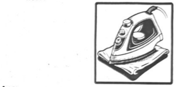
Thus, the electric iron will consume 5.04 MJ of electrical energy in an hour.
GIVEN:
- Resistance ‘R’ = 19 Ω
- Voltage ‘V’ = 200 V
REQUIRED:
- Electric Power ‘P’ = ?
SOLUTION:
By Ohm’s law, the current ‘I’ is: $I = \frac{V}{R}$
Putting values: $I = \frac{200\,\text{V}}{19\,\Omega}$ or $I = 10.5\,\text{A}$
The power ‘P’ can now be obtained by multiplying current and voltage, as:
$$P = IV$$
Putting values: $P = (10.5\,\text{A}) \times (200\,\text{V})$
Therefore, $P = 2100\,\text{W}$ [ANSWER]
The power consumption of an electric toaster is 2100 W if its resistance is 19 Ω.
GIVEN:
- Resistance ‘R’ = 100 Ω
- Rated Power ‘PR’ = 0.5 W
- Connected voltage ‘V’ = 10 V
REQUIRED:
- Power dissipated ‘P’ = ?
SOLUTION:
We would calculate the amount of heat dissipated in resister by using formula for power dissipated in resistor.
$$P = \frac{V^2}{R}$$
Putting values: $P = \frac{(10\,\text{V})^2}{100\,\Omega}$
Therefore, $P = 1\,\text{W}$ [ANSWER]
Because the resistor has a power rating of 1/2 W, and the amount of heat that will be dissipated is 1 W, the resistor will it be damaged.

GIVEN:
- Electric power ‘P’ = 2200 W = 2.2 kW
- Monthly Time ‘t’ = 30 × 24 hours = 720 h
- Tariff rate = PKR 25.0 / kWh
REQUIRED:
- Energy consumed in kWh ‘E’ = ?
- Cost of electricity ‘C’ = ?
SOLUTION:
The electric power is given by: $P = \frac{E}{t}$ or $E = P \times t$
Putting values: $E = 2.2\,\text{kW} \times 720\,\text{h}$
Therefore, $E = 1584\,\text{kWh}$ [ANSWER]
The total consumed energy is 1584 kWh (or 1584 commercial units), the cost of which can be calculated as:
⇒ Cost = E × Tariff Rate = (1584 kWh) × (PKR 25.0)
⇒ Cost = 39,600 rupees
The cost of electricity for an AC for the whole month is PKR 39,600.
Summary
- Electric Circuit is a closed pathway through which electricity flows, typically consisting of a power source, wires, and components like resistors.
- Resistor is an electrical component that limits the flow of electric current in a circuit, measured in ohms (Ω).
- Series Combination of Resistors include connecting resistors end-to-end in a single path so that the same current flows through each.
- Parallel Combination of Resistors include connecting resistors side by side across the same voltage source, allowing multiple current paths.
- Potential Divider is a circuit arrangement used to divide a voltage into smaller fractions using resistors connected in series.
- Electric Power is the rate at which electrical energy is transferred or consumed in a circuit, measured in watts (W).
- Electrical Energy is the ability of electricity to do work or produce heat, measured in joules (J) or kilowatt-hours (kWh).
- Kilowatt Hour (kWh) is the unit of electrical energy commonly used to measure consumption or production over time, equal to one kilowatt of power used for one hour.
- Electricity and Its Uses include flow of electric charge through conductive materials, utilized for heating, lighting, powering devices, and various applications.
- Electrical Safety involves the practices and measures to prevent accidents and injuries related to electricity, including proper installation, maintenance, and following safety guidelines.