
1. Two resistances of 4 ohm are connected in parallel and this combination is connected to another 6 ohm resistance in series. The equivalent resistance will be:
2. In series connection of resistors, the current across each resistor:
3. A resistor’s first three colours are brown, black and red, its value is:
4. The relation for electric power in a circuit is $P =$ ______.
5. In the given figure, the current passing through 6 Ω resistor is:

6. When four cells, each with an e.m.f of 0.5 V, are connected in parallel, the net e.m.f is:
7. The purpose of grounding electrical systems is to:
8. The purpose of a circuit breaker is to:
9. Which electrical element control the flow of the electric current in a circuit?
10. A and B are two bulbs connected in parallel. A is glowing brighter than B, then the relation between $R_A$ and $R_B$ is:
11. The S.I unit for electrical power is:
12. A wire of resistance R is divided in 10 equal parts. These parts are connected in parallel, the equivalent resistance of such connection will be:
Constructed Response Questions:
Q1. A battery of voltage V is connected to 30 W bulb and 60 W bulb as shown in the figure, (a) Identify brightest bulb (b) Which bulb has greater resistance? (c) Suppose the two bulbs are connected in series, which bulb will glow brighter?
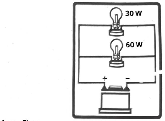
Given
Two light bulbs connected to a voltage $V$.
- Bulb 1: $P_1 = 30\,W$
- Bulb 2: $P_2 = 60\,W$
(a) Identify the brightest bulb (when connected in parallel):
In parallel, voltage $V$ is constant for both bulbs.
Power $P = \frac{V^2}{R}$ implies $P \propto \frac{1}{R}$.
Higher power means brighter glow.
The 60 W bulb has higher power, so it glows brighter.
(b) Which bulb has greater resistance?
Determine which bulb has greater resistance.
Using $P = \frac{V^2}{R}$, resistance $R = \frac{V^2}{P}$.
Since $V$ is constant, $R \propto \frac{1}{P}$.
The 30 W bulb has lower power, so it has greater resistance.
(c) Suppose the two bulbs are connected in series, which bulb will glow brighter?
Identify the brightest bulb in series.
In series, current $I$ is constant for both bulbs.
Power $P = I^2R$ implies $P \propto R$.
The bulb with greater resistance will dissipate more power and glow brighter.
The 30 W bulb has greater resistance, so it will glow brighter in series.
Therefore,
(a) The 60 W bulb is brighter in parallel; (b) The 30 W bulb has greater resistance; (c) The 30 W bulb will glow brighter in series.
Q2. What is the value of resistance of the following resistors?
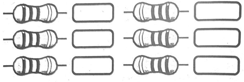
Resistor Color Code:
- Brown = 1
- Black = 0
- Red = 2 (multiplier: $10^2$)
- Orange = 3 (multiplier: $10^3$)
- Yellow = 4
- Green = 5
- Blue = 6
- Purple = 7
- Silver = Tolerance ±10%
- Gold = Tolerance ±5%
Resistor 1 (Left, Top): Brown, Black, Red, Orange
- 1st band: Brown = 1
- 2nd band: Black = 0
- 3rd band: Red = $10^2$ = 100
- 4th band: Orange Tolerance
- Resistance: $10 \times 10^2 = 1000\,\Omega = 1\,k\Omega$
Resistor 2 (Left, Middle): Yellow, Red, Green, Silver
- 1st band: Yellow = 4
- 2nd band: Red = 2
- 3 rd band: Green = $10^5$ = 100,000
- 4 th band: Silver = Tolerance ±10%
- Resistance: $42 \times 10^5 = 4{,}200{,}000\,\Omega = 4.2\,M\Omega$
Resistor 3 (Left, Bottom): Yellow, Yellow, Purple, Orange
- 1st band: Yellow = 4
- 2nd band: Yellow = 4
- 3rd band: Purple = $10^7$ = 10,000,000
- 4th band: Orange Tolerance
- Resistance: $44 \times 10^7 = 4{,}400{,}000{,}000\,\Omega = 4.4\,G\Omega$
Resistor 4 (Right, Top): Brown, Blue, Yellow, Silver
- 1st band: Brown = 1
- 2nd band: Blue = 6
- 3rd band: Yellow = 104 = 10,000
- 4th band: Silver = Tolerance ±10%
- Resistance: 16 × 104 = 160,000 Ω = 160 kΩ
Resistor 5 (Right, Middle): Silver, Purple, Yellow, Orange
A silver first band is not a valid resistor. It seems there may be an issue with the resistor’s color bands, or the colors are not being read correctly.
Resistor 6 (Right, Bottom): Blue, Yellow, Orange, Silver
- 1st band: Blue = 6
- 2nd band: Yellow = 4
- 3rd band: Orange = 103 = 1,000
- 4th band: Silver = Tolerance ±10%
- Resistance: 64 × 103 = 64,000 Ω = 64 kΩ
Summary of Resistance Values:
- Resistor 1: 1 kΩ
- Resistor 2: 4.2 MΩ
- Resistor 3: 4.4 GΩ
- Resistor 4: 160 kΩ
- Resistor 5: Invalid
- Resistor 6: 64 kΩ
Q3. Calculate the equivalent resistance between points A and B in the given circuit.

The circuit consists of three sets of parallel resistors connected in series.
- Set 1: Two 2 Ω resistors in parallel
- Set 2: Two 4 Ω resistors in parallel
- Set 3: Two 6 Ω resistors in parallel
First, calculate the equivalent resistance for each parallel set:
1/Re = 1/R1 + 1/R2; therefore, Re = (R1 × R2)/(R1 + R2)
- Set 1: R1eq = (2 × 2)/(2 + 2) = 4/4 = 1 Ω
- Set 2: R2eq = (4 × 4)/(4 + 4) = 16/8 = 2 Ω
- Set 3: R3eq = (6 × 6)/(6 + 6) = 36/12 = 3 Ω
Now, since these equivalent resistances are connected in series, we add them up:
RAB = R1eq + R2eq + R3eq = 1 + 2 + 3 = 6 Ω
Therefore, the equivalent resistance between points A and B is 6 Ω.
Q4. Consider a circuit in which a heater is in series with the supply voltage. Which device out of the following should be placed to present a higher resistance initially, preventing large currents from flowing at turn-on?
Short Questions:
Q1. How does the color code on a carbon resistor provide information about its properties, and why is this method chosen over other labeling techniques?
Carbon resistors utilize a color code system because their small size makes it impractical to print resistance values directly on them. The color bands represent numerical values and multipliers, allowing for quick and easy identification of resistance and tolerance, which is especially useful in automated production lines. This method is chosen over printing because it’s more space-efficient, readable regardless of resistor orientation, and compatible with automated machinery.
How it works:
Bands and Values:
Resistors have a series of colored bands, typically three or four, with each color corresponding to a specific digit or multiplier. The color code on a carbon resistor provides information about its resistance value and tolerance.
Typically, a resistor has 4 or 5 color bands:
- 1st and 2nd Bands: These represent the first two digits of the resistance value.
- 3rd Band: This represents the multiplier, which is the power of 10 by which the first two digits must be multiplied.
- 4th Band: This represents the tolerance, which indicates the percentage by which the actual resistance value may vary from the indicated value. Common tolerance values are gold (± 5%), silver (± 10%), and no band (± 20%).
- Resistance Calculation: The first two bands represent the first two significant figures of the resistance value, while the third band indicates the number of zeros to be added (or the multiplier).
- Tolerance: The fourth band (if present) indicates the tolerance, which is the percentage of acceptable deviation from the stated resistance value.
- Examples: A resistor with bands of brown, black, red, and gold would translate to 10 × 100 ohms with a 5% tolerance, resulting in a resistance of 1000 ohms (1 kΩ) with a 5% margin of error.
Why color coding is preferred:
- Small Size: Carbon resistors, especially those used in through-hole circuits, are often too small to print numerical values legibly.
- Ease of Identification: Color bands are easily visible and readable, regardless of how the resistor is oriented on the circuit board.
- Automated Assembly: Automated machinery can easily identify and pick up resistors based on the color code.
- Cost-Effective: Printing numerical values on such small components would be more expensive than applying colored bands.
- Global Standard: Color coding is a standardized system, making it universally understood and used.
Q2. Why are electrical devices in homes connected in parallel rather than in series? How would household functionality be impacted if they were connected in series?
Electrical devices in homes are connected in parallel because it allows them to operate independently and at their intended voltage. If they were connected in series, all devices would need to be turned on for any to function, and the voltage would be divided among them, likely resulting in dim or non-functional appliances.
Parallel Connection (How it works in homes):
- Each device receives the full voltage from the power source (e.g., 120 V or 240 V in most homes).
- If one device fails or is switched off, the others continue to work because they have their own path to the power source.
- This allows for individual control of appliances and flexibility in how the electrical system is used.
Series Connection (If used in homes):
- The voltage from the power source is divided among all the devices in the circuit.
- If one device fails or is switched off, the entire circuit is broken, and all other devices stop working.
- For example, if two lamps were connected in series to a 120 V source, each lamp would only receive 60 V, which would likely result in them being very dim or not lighting at all.
- Furthermore, all devices would need to be turned on simultaneously for any to function, which is impractical.
- This configuration would also limit the ability to control devices individually. In essence, parallel circuits provide the flexibility, independent operation, and constant voltage needed for safe and convenient use of electrical devices in a home.
Q3. When resistors are connected in parallel, why does the total resistance decrease? How does this principle relate to the efficiency of electrical systems?
In a parallel circuit, adding resistors decreases the total resistance because it provides more pathways for current to flow. Each resistor offers an alternative route, effectively reducing the overall opposition to the current’s movement. This principle is crucial for enhancing the efficiency of electrical systems by minimizing energy losses due to resistance and optimizing power delivery.
Explanation:
- Parallel Paths: When resistors are connected in parallel, the current divides and flows through each resistor independently. This creates multiple paths for the current to travel, increasing the overall conductivity of the circuit.
- Reduced Opposition: Since the current has more pathways to choose from, the total resistance encountered by the current decreases. Imagine a busy highway; if you add more lanes, traffic flows more easily, even if the individual lanes still offer some resistance.
- Mathematical Relationship: When resistors are connected in parallel, you are essentially providing more paths for the current to flow. The reciprocal of the equivalent resistance of parallel resistors is equal to the sum of the reciprocals of the individual resistances:
$$\frac{1}{R_{\mathrm{eq}}}=\frac{1}{R_1}+\frac{1}{R_2}+\frac{1}{R_3}+\cdots$$
This means that the total resistance ($R_{\mathrm{eq}}$) will always be less than the smallest individual resistance in the parallel combination.
- Efficiency in Electrical Systems: Lower resistance in parallel circuits leads to reduced energy loss as heat, as less power is dissipated by the resistors. This improved efficiency is particularly important in power distribution networks and electronic circuits, where minimizing energy waste is crucial for optimal performance.
How it relates to efficiency:
- Reduced Voltage Drop: In parallel circuits, the voltage drop across each branch is the same as the source voltage. This means that the voltage is effectively maintained across each component, preventing significant drops that could reduce their functionality or efficiency.
- Optimized Power Delivery: By reducing resistance, parallel circuits allow for higher current flow at a given voltage. This can be leveraged to deliver more power to devices or components, improving their performance and overall system efficiency.
- Enhanced Reliability: In parallel circuits, if one resistor fails or becomes disconnected, the remaining resistors can still function, ensuring continued operation of the circuit. This redundancy enhances the reliability and robustness of the electrical system.
Example:
Consider a string of Christmas lights. If the lights are connected in series, and one light burns out, the entire string goes dark. However, if the lights are connected in parallel, a single burnt-out bulb will not affect the others. This demonstrates how parallel connections can improve the reliability of an electrical system.
In summary, the decrease in resistance in parallel circuits is due to the availability of multiple current pathways, which allows for easier current flow and minimizes energy losses. This principle is essential for designing efficient and reliable electrical systems across various applications.
Q4. How incorrect parallel placement of ammeters can damage circuits, suggesting ways to prevent this.
Incorrect parallel placement of an ammeter in a circuit can lead to damage because ammeters have very low resistance. When placed in parallel, this low resistance allows a large current to flow through the ammeter, potentially causing it to overheat, burn out, or even trigger a short circuit, blowing fuses or damaging other components. To prevent this, ammeters should always be connected in series with the component whose current is being measured.
Why parallel connection damages circuits:
- Low resistance: Ammeters are designed with very low internal resistance to minimize their impact on the circuit they are measuring.
- Short circuit effect: When an ammeter is connected in parallel with a voltage source or a component, it creates a low-resistance path for the current to flow. This path bypasses the intended load, causing a large surge of current through the ammeter.
- Overheating and damage: The excessive current flow can lead to overheating of the ammeter’s internal components, potentially causing it to burn out or even short circuit.
- Circuit disruption: A short circuit caused by an improperly placed ammeter can disrupt the entire circuit, leading to blown fuses, tripped circuit breakers, or even damage to other components.
How to prevent damage:
- Series connection: Always connect the ammeter in series with the component you want to measure the current of. This ensures that the entire current flowing through that component also passes through the ammeter.
- Proper range: Use an ammeter with a current range suitable for the expected current in the circuit.
- Observe polarity: Pay attention to the polarity markings on the ammeter and ensure it is connected correctly in the circuit.
- Consult documentation: Refer to the manufacturer’s documentation for your specific ammeter for detailed instructions and safety precautions.
- Disconnect before adjustments: Always disconnect the power source before making any changes to the circuit or connections.
Q5. Why is it unsafe to touch electrical switches with wet hands? What principles of conductivity and human safety does this advice rely on?
Touching electrical switches with wet hands is unsafe because water significantly reduces the electrical resistance of the human body, making it a better conductor of electricity. This increases the risk of electric shock, which can range from mild to severe depending on factors like voltage and the path of the current through the body.
Here’s a breakdown of the principles involved:
- Water’s Conductivity:
- Pure water is a poor conductor of electricity. However, ordinary water (like tap water) contains dissolved minerals and salts, making it a relatively good conductor.
- When water comes into contact with electrical components, it can create a conductive pathway for electricity to flow.
- Human Body’s Conductivity:
- The human body is composed of a significant amount of water, making it a relatively good conductor of electricity, especially when wet.
- Wet skin and especially wet hands reduce the body’s electrical resistance, meaning electricity can flow through the body more easily.
- The Danger of Electric Shock:
- When a person with wet hands touches a live electrical switch, the electricity can flow through the water on their hands, through their body, and potentially to the ground (if they are also standing on a wet surface).
- This flow of electricity can cause electric shock, which can range from a tingling sensation to muscle spasms, burns, cardiac arrest, or even death.
- Safety Measures:
- Always ensure your hands are dry before touching any electrical appliance or switch.
- Avoid using electrical appliances in wet areas or near water sources.
- If you suspect an electrical problem, turn off the power at the main breaker before attempting any repairs.
- If you are working on electrical equipment, wear appropriate safety gear, including insulated gloves and shoes.
Q6. What makes touching a live wire while barefoot on the ground particularly dangerous? How do the factors involved influence the severity of electrical shock?
It is dangerous to touch a live wire while standing barefoot on the ground because the human body is a conductor of electricity. When a person is barefoot on the ground, they create a path for electricity to flow through their body to the ground, which is known as being grounded.
Touching a live wire while barefoot on the ground is particularly dangerous due to the following reasons:
- Direct Path to Ground: When you’re barefoot, your skin has direct contact with the Earth. The ground serves as a large, conductive body that is considered to be at zero potential (ground potential). If you touch a live wire, which has a high potential, your body provides a direct, low-resistance path for current to flow from the wire, through your body, and into the ground.
- Reduced Resistance: Dry skin has a relatively high electrical resistance, which limits the current that can flow through the body. However, when barefoot, the soles of your feet may be damp or sweaty, which significantly reduces the skin’s resistance. This allows a larger current to flow through your body compared to wearing shoes with insulating soles.
- Proximity to Ground: Being in direct contact with the ground ensures that there is a significant potential difference between the live wire and your body. This high potential difference drives a larger current through your body.
Factors Influencing the Severity of Electrical Shock
The severity of an electrical shock depends mainly on:
- Current Amount: Higher current is more dangerous.
- Current Path: Current through the heart or brain is most critical.
- Duration: Longer contact increases damage.
- Voltage: Higher voltage drives more current.
Q7. How does a circuit breaker protect a household’s electrical system? What might happen in the absence of a circuit breaker during a power surge or overload?
Circuit breakers are crucial for protecting a home’s electrical system by preventing fires and damage during power surges or overloads. They automatically shut off the power when they detect excessive current, preventing wires from overheating and potentially causing a fire. Without circuit breakers, a power surge or overload could lead to overheating, arcing, and potentially devastating electrical fires, as well as damage to appliances and electronics.
Here’s a more detailed explanation:
How circuit breakers protect:
- Overload Protection: When too many appliances are used on the same circuit, the current draw exceeds the circuit’s capacity. The breaker detects this overload and trips, cutting off the power to prevent overheating and potential fires.
- Short Circuit Protection: A short circuit occurs when a “hot” wire accidentally touches a neutral or ground wire. This creates a low-resistance path for current to flow, leading to a large surge. The breaker quickly trips to stop the flow of excessive current.
- Ground Fault Protection: Ground fault circuit interrupters (GFCIs) are a type of circuit breaker that protect against ground faults, which occur when
Consequences of no circuit breakers:
- Fires: Without circuit breakers, overloaded circuits and short circuits can cause wires to overheat and potentially ignite nearby materials, leading to electrical fires.
- Damage to Appliances and Electronics: Power surges can damage or destroy sensitive electronics and appliances, causing costly repairs or replacements.
- Electrical Shock and Electrocution: In the absence of circuit breakers, there is a greater risk of electrical shock and electrocution, especially with ground faults.
In short, a circuit breaker acts as an essential safety switch, preventing electrical fires and equipment damage by automatically cutting power when the current becomes dangerously high.
Q8. In what ways does grounding an applications case enhance user safety? How does grounding mitigate potential electrical hazards?
Grounding an appliance case significantly enhances user safety by providing a low-resistance path for fault currents to flow directly to the earth, thus preventing electric shock and reducing the risk of electrical fires. If a live wire accidentally contacts the appliance’s metal casing, the grounded connection ensures that the fault current is safely channeled to the ground, triggering a circuit breaker or fuse to trip and disconnect the power.
Detailed explanation:
- Preventing electric shock: Grounding ensures that the appliance’s metal casing remains at or near ground potential, which is the same as the potential of the earth. If a person touches the casing while it is energized due to a fault, the current will flow through the grounding path rather than through the person’s body, minimizing the risk of shock.
- Mitigating fire hazards: Fault currents can generate significant heat, potentially igniting nearby flammable materials and causing a fire. Grounding provides a low-resistance path for these fault currents to flow to the ground, minimizing the heat generated and reducing the risk of fire.
- Ensuring proper operation of safety devices: Grounding also helps ensure that circuit protection devices like circuit breakers and fuses operate correctly. When a fault occurs, the ground wire provides a path for the fault current to flow, which trips the protective device and disconnects the power, preventing further damage and hazards.
- Stabilizing voltage levels: Grounding contributes to a more stable voltage level in the electrical system, which is crucial for the proper and safe operation of appliances and other electrical equipment.
Grounding mitigates electrical hazards by providing a safe, low-resistance path for excess electrical current to flow to the earth, preventing dangerous shocks and fires. This mechanism ensures that in case of a fault (like a short circuit), the current is safely diverted away from people and appliances, minimizing the risk of harm and damage.
Q9. How does an appliance’s wattage influence its energy consumption and operational cost? How can understanding this relationship help in making energy-efficient choices?
An appliance’s wattage directly impacts its energy consumption and operational cost. Higher wattage means the appliance uses more electricity per unit of time (e.g., per hour), directly translating to higher energy bills. Understanding this relationship is crucial for making energy-efficient choices by identifying appliances that consume less power for the same function.
How Wattage Affects Energy Consumption and Cost:
- Wattage as Power Consumption: Wattage is a measure of how much power an appliance uses. A higher wattage indicates greater power consumption.
- Energy Consumption: Energy consumption is measured in kilowatt-hours (kWh), and it’s calculated by multiplying the wattage by the time the appliance is used.
- Operational Cost: The cost of running an appliance is directly proportional to its energy consumption. If two appliances perform the same function, the one with higher wattage will consume more energy and thus cost more to operate.
The relationship is:
$$E = P \times t$$
The cost is calculated as:
$$\text{Cost} = E \times (\text{Price per kWh})$$
$$\text{Cost} = (P_{\mathrm{kW}} \times t_{\mathrm{hours}}) \times (\text{Price per kWh})$$
How Understanding Wattage Helps in Making Energy-Efficient Choices:
- Choosing Lower Wattage Appliances: When replacing or purchasing new appliances, consider models with lower wattage ratings for the same functionality. This will significantly reduce your energy consumption and costs.
- Comparing Appliances: Wattage can be a key factor in comparing similar appliances. For example, compare the wattage of different models of refrigerators or washing machines to determine which one is more energy-efficient.
- Monitoring Energy Consumption: By knowing the wattage of your appliances and monitoring their usage, you can better understand your overall energy consumption and identify areas where you can reduce usage and save money.
- Considering Efficiency Ratings: Look for appliances with Energy Star certifications, as these are designed to use less energy for the same output compared to standard models.
Q10. In what ways do electrical energy and electrical power differ in function and application? How do these differences impact our understanding and measurement of electricity?
Electrical energy and electrical power are related but distinct concepts. Electrical energy is the capacity to do work, while electrical power is the rate at which that work is done or energy is transferred. Essentially, energy is the “amount” of electrical work, and power is the “speed” at which that work is performed.
Detailed breakdown:
(i) Electrical Energy:
- Definition: The ability of charged particles to cause motion or action, or the capacity to do work.
- Measurement: Typically measured in Joules (J) or kilowatt-hours (kWh).
- Analogy: Imagine a battery as a storage container of energy. The total amount of electricity it can deliver is its energy capacity.
- Function: Used to power devices, perform tasks, and drive processes.
- Application: Everything from lighting a bulb to running a motor, or powering a computer relies on electrical energy.
(ii) Electrical Power:
- Definition: The rate at which electrical energy is transferred or used.
- Measurement: Typically measured in Watts (W), which is Joules per second (J/s).
- Analogy: Think of the speed at which the battery’s stored energy is used. A powerful appliance uses its energy faster than a less powerful one.
- Function: Determines how quickly a device can do work or consume energy.
- Application: Influences how fast a motor can spin, how quickly a light bulb illuminates, or how much power a device requires at any given moment.
Impact on Understanding and Measurement:
- Energy bills: Understanding the difference between power and energy is crucial for reading and understanding electricity bills, which typically charge based on energy consumption (kWh).
- Appliance selection: Choosing appliances with appropriate power ratings (watts) is important for ensuring they function correctly and efficiently within the available electrical system.
- Energy management: Understanding the relationship between power and energy helps in managing energy consumption, such as identifying areas where energy waste can be reduced.
- System design: Electrical engineers need to understand both power and energy to design efficient electrical systems, considering factors like voltage drop, current flow, and power factor.
Key Relationship:
Power (watts) = Energy (joules) / Time (seconds)
and Energy (joules) = Power (watts) × Time (seconds)
In essence, power is a measure of how quickly energy is being used, while energy is the total amount of electricity consumed over a period.
Q11. How does the kilowatt-hour serve as a unit of energy consumption, and what steps can you take to convert energy usage from joules to kilowatt-hours?
A kilowatt-hour (kWh) measures energy consumption, specifically the amount of energy used by a 1 kilowatt (kW) device operating for one hour. To convert joules to kilowatt-hours, divide the energy value in joules by 3,600,000 (since 1 kWh equals 3.6 million joules).
How the Kilowatt-Hour Serves as a Unit of Energy Consumption:
- Definition: The kilowatt-hour is a unit of energy. It represents the amount of energy consumed when a device with a power rating of 1 kilowatt (kW) operates for a duration of 1 hour.
- Derivation: It comes directly from the relationship between energy (E), power P, and time (t).
E = P × t
If power is measured in kilowatts (kW) and time is measured in hours (h), then the resulting energy unit is the kilowatt-hour (kWh).
- Practicality: While the standard SI unit for energy is the Joule (J), the Joule is often too small for practical measurements of household or industrial electricity consumption. For example, a simple 100 W light bulb running for 1 hour consumes:
E = P × t = 100 W × 3600 s = 360,000 J
Using kWh simplifies this:
E = P × t = 0.1 kW × 1 h = 0.1 kWh
Utility companies use kWh for billing because it yields more manageable numbers that directly relate to the power ratings of appliances and the time they are used.
Steps to Convert Energy Usage from Joules (J) to Kilowatt-Hours (kWh):
To convert from Joules to kWh, you need to know the conversion factor:
- Establish the Relationship:
- Recall that 1 kW = 1000 W.
- Recall that 1 hour = 3600 seconds.
- Recall that 1 Watt = 1 Joule per second (1 W = 1 J/s).
- Calculate the Conversion Factor:
⇒ 1 kWh = 1 kW × 1 h
⇒ 1 kWh = (1000 W) × (3600 s)
⇒ 1 kWh = 1000 J/s × 3600 s
- To convert an energy value from Joules ($E_J$) to kilowatt-hours ($E_{kWh}$), you divide the value in Joules by the number of Joules in one kilowatt-hour.
- Step 1: Take the energy value in Joules ($E_J$).
- Step 2: Divide this value by 3,600,000 (or $3.6 \times 10^6$).
- Formula: $E_{kWh} = \frac{E_J}{3,600,000}$
- Example: Convert 18,000,000 Joules to kWh.
$E_{kWh} = \frac{18,000,000\ \mathrm{J}}{3,600,000\ \mathrm{J/kWh}} = 5\ \mathrm{kWh}$
Q12. Describe a situation in your daily life where electrical energy is essential. How does this energy transform to allow the device to perform its function?
Situation:
Making a cup of tea or coffee in the morning. Electrical energy is essential to heat the water quickly and conveniently using an electric kettle. Without it, you’d have to use a stovetop kettle, which relies on chemical energy from gas or other fuels.
Energy Transformation:
Electrical Energy Input:
When you plug in the kettle and switch it on, electrical energy flows from the wall socket, through the power cord, into the kettle’s heating element. This energy is carried by moving electrons within the wires.
Transformation to Thermal Energy:
The heating element inside the kettle is specifically designed to have high electrical resistance. As the electrical current (flow of electrons) is forced through this resistant material, the electrons collide with the atoms of the element. These collisions cause the atoms to vibrate more vigorously. This increased atomic vibration is thermal energy (heat). According to Joule’s law of heating, the heat generated is proportional to the square of the current, the resistance, and the time ($H \propto I^2Rt$).
Heat Transfer:
The thermal energy generated in the heating element is then transferred to the water inside the kettle, primarily through conduction and convection. The hot element heats the water it’s in contact with, and convection currents circulate the water, distributing the heat until the entire volume reaches boiling point.
Output:
The primary useful output is hot water (thermal energy stored in the water). Some energy is also inevitably converted into sound energy (the boiling noise) and some heat is lost to the surrounding air and the kettle body itself (waste heat).
So, the essential energy transformation in an electric kettle is:
Electrical Energy → Thermal Energy (in the heating element) → Thermal Energy (in the water)
Q13. What are three common sources of electrical energy, and how do their advantages and disadvantages influence our choice of energy sources?
Three common sources of electrical energy are coal, nuclear, and solar power. Their advantages and disadvantages significantly influence the choice of energy sources, with coal being inexpensive but polluting, nuclear being energy-dense but risky, and solar being clean but intermittent.
Coal:
- Advantages: Coal is relatively inexpensive to mine and widely available, making it a cost-effective option for electricity generation.
- Disadvantages: Burning coal releases large amounts of greenhouse gases and pollutants, contributing to climate change and air pollution. Coal mining can also have significant environmental impacts on the surrounding landscape.
Nuclear:
- Advantages: Nuclear power plants produce vast amounts of electricity with minimal greenhouse gas emissions. Nuclear energy is also very energy-dense, meaning a small amount of fuel can generate a large amount of power.
- Disadvantages: Nuclear power plants pose risks of accidents, such as meltdowns or radioactive contamination. The disposal of nuclear waste is another significant challenge, as it remains radioactive for thousands of years.
Solar:
- Advantages: Solar power is a clean and renewable energy source, meaning it doesn’t produce greenhouse gases or pollutants. Solar energy is also widely available, with new technologies making it more efficient and cost-effective.
- Disadvantages: Solar energy is intermittent, meaning it is only available when the sun is shining. Solar power also requires a large land area for solar farms.
Hydropower:
Hydropower is a renewable energy source that generates electricity by harnessing the power of moving water. This is typically achieved by using dams to create reservoirs that store water and then releasing the water to turn turbines connected to generators, thus producing electricity.
How Hydropower works:
Water Storage:
Hydropower plants often rely on dams to create reservoirs that store a large volume of water.
Potential Energy:
The stored water possesses potential energy due to its height above the turbines.
Conversion to Kinetic Energy:
When water is released from the reservoir, it flows through penstocks (large pipes) and its potential energy is converted into kinetic energy as it moves.
Turbine Rotation:
The flowing water then strikes the blades of a turbine, causing it to rotate.
Electricity Generation:
The rotating turbine is connected to a generator, which converts the mechanical energy of the turbine into electrical energy.
Advantages of Hydropower:
- Renewable Energy Source: Hydropower relies on the water cycle, which is constantly replenished by the sun, making it a sustainable energy source.
- Clean Energy Source: Hydropower plants do not produce greenhouse gas emissions during electricity generation.
- Reliable Energy Source: Hydropower can provide a consistent and reliable supply of electricity, especially when paired with pumped storage systems.
- Multiple Benefits: Hydropower dams can also provide benefits like water supply regulation, flood control, and irrigation.
Disadvantages of Hydropower:
- Environmental Impact: Dam construction can disrupt river ecosystems and impact fish migration.
- High Upfront Costs: Building hydropower plants, especially large-scale ones, can require significant upfront investment.
- Dependence on Water Availability: Hydropower production is influenced by rainfall and water availability, which can vary seasonally and regionally.
Q14. Examine the effects and risks of connecting different e.m.f. sources in parallel, and suggest safe ways to combine power sources.
Connecting e.m.f. sources with different voltages in parallel is generally not recommended and can be dangerous. It can lead to damage to the lower voltage source or even a short circuit due to current flowing from the higher voltage source into the lower one. Instead, safe parallel connection requires careful matching of voltage and consideration of internal resistance.
Effects and Risks of Connecting Different EMF Sources in Parallel:
- Current Flow from Higher to Lower: If the EMFs are different, the source with the higher voltage will try to force current into the source with the lower voltage.
- Potential for Short Circuit: This current flow can create a short circuit condition, potentially damaging the components and creating a safety hazard.
- Overheating and Failure: The unequal voltage and current flow can lead to overheating and eventual failure of the power sources.
- Reduced Voltage: If the EMF sources are not identical, the resulting voltage in the parallel combination may be lower than the voltage of the highest source, depending on their internal resistances.
Safe Ways to Combine Power Sources in Parallel:
Matching Voltages:
The most crucial aspect is ensuring that all voltage sources connected in parallel have the same voltage rating.
Consider Internal Resistance:
When connecting batteries or other power sources in parallel, their internal resistances should be considered. If internal resistances are significantly different, even with the same voltage, there can be issues with current distribution and heat generation.
Use of Diodes:
In some cases, diodes can be used to prevent backflow of current from one source to another, especially when dealing with batteries that might have slightly different voltage characteristics.
Load Sharing Devices:
Specialized devices like load sharing controllers can be used to manage the current flow from multiple sources, ensuring a more balanced and safe operation.
Series-Parallel Combinations:
For higher voltage or current requirements, series-parallel combinations can be employed, where groups of sources are connected in series within a larger parallel configuration.
Consult with an Expert:
For complex setups or when dealing with high-power applications, consulting with an electrical engineer or other qualified professional is highly recommended.
In summary: While parallel connections can increase current capacity, connecting different voltage sources in parallel can be very risky. Matching voltages, considering internal resistance, and potentially using specialized devices like diodes or load sharing controllers are essential for safe and reliable operation.
Long Questions:
Q1. What is the significance of different types of resistors in electronic circuits, and how do their characteristics influence circuit design?
Resistors are fundamental components in electronic circuits, with various types offering unique characteristics that significantly influence circuit design. They control current flow, divide voltage, and can be used to implement specific functionalities like temperature or light sensing. Understanding these characteristics, such as resistance value, tolerance, power rating, and temperature dependence, is crucial for selecting the right resistor for a given application and ensuring optimal circuit performance.
Significance of Resistor Types:
- Fixed Resistors: These maintain a constant resistance value and are used for general current limiting, voltage division, and biasing active components. Examples include carbon composition, metal film, and wire-wound resistors, each offering different levels of precision, stability, and power handling.
- Variable Resistors (Potentiometers / Rheostats): These allow for adjustable resistance, enabling functions like volume control, brightness adjustment, and calibration.
Special Purpose Resistors:
- Thermistors: Resistance changes with temperature, making them suitable for temperature sensing and compensation.
- Varistors: Resistance changes with voltage, used for surge protection and overvoltage protection.
- Light-Dependent Resistors (LDRs): Resistance changes with light intensity, used in light-sensitive circuits and sensors.
Influence on Circuit Design:
- Current Limiting: Resistors limit the current flowing through a circuit, protecting components from damage due to excessive current or voltage.
- Voltage Division: Resistors can be arranged in a voltage divider network to create specific voltage levels within a circuit, essential for signal conditioning and level shifting.
- Power Dissipation: Resistors dissipate electrical energy as heat, and their power rating must be sufficient to handle the expected power dissipation without overheating or failing.
- Signal Conditioning: Resistors can be used to shape and modify signals in various circuits, such as filters and amplifiers.
- Stability and Precision: The choice of resistor type affects circuit stability and precision, with metal film resistors offering better stability and accuracy than carbon composition resistors.
- Noise Characteristics: Different resistor types exhibit varying noise levels, which can be crucial in sensitive circuits like audio amplifiers.
- Temperature Dependence: Some applications require resistors with low temperature coefficients to maintain stable performance over a range of temperatures.
Q2. Explain the principles behind the series combination of resistances and illustrate how the total resistance changes when more resistors are added?
In a series combination of resistors, the total resistance increases as more resistors are added. This is because the current has to flow through each resistor sequentially, increasing the overall opposition to current flow.
Principles of Series Resistance:
- Same Current: In a series circuit, the same amount of current flows through each resistor.
- Voltage Division: The voltage from the power source is divided among the resistors. The voltage drop across each resistor depends on its resistance value.
- Total Resistance: The total resistance ($R_{\text{total}}$) of resistors in series is the sum of individual resistances:
$$R_{\text{total}} = R_1 + R_2 + \cdots + R_n$$
How Adding Resistors Affects Total Resistance:
- Increased Resistance: Adding more resistors in series increases the total resistance of the circuit.
- Decreased Current: With increased resistance, the overall current flowing through the circuit decreases, as the circuit becomes more difficult for current to flow.
- Example: If you have a 2 Ω resistor and add a 4 Ω resistor in series, the total resistance becomes 6 Ω (2 Ω + 4 Ω). Adding another 6 Ω resistor in series would result in a total resistance of 12 Ω (6 Ω + 6 Ω).
Adding another resistor in series always increases the total resistance of the circuit. Each resistor added contributes its full resistance value to the overall sum, further impeding the flow of current for a given total voltage.
Q3. How does the concept of equivalent resistance in parallel circuits differ from that in series circuits, and what practical applications can you identify for each?
In series circuits, equivalent resistance is the sum of individual resistances, while in parallel circuits, it’s less than the smallest resistance due to the reciprocal relationship of the resistances.
Series circuits are used where a single path for current flow is desired, like in some lighting circuits, while parallel circuits offer multiple paths and are used when individual component failure shouldn’t interrupt the entire circuit, such as in household wiring.
Series Circuits:
- Concept: In a series circuit, components are connected end-to-end, forming a single path for current to flow.
- Equivalent Resistance: The equivalent resistance ($R_{\text{eq}}$) is the sum of all individual resistances:
$$R_{\text{eq}} = R_1 + R_2 + \cdots + R_n$$
Practical Applications:
- Simple Lighting Circuits: Old-fashioned Christmas lights, where if one bulb fails, they all go out.
- Voltage Dividers: Used to create specific voltage levels from a higher voltage source.
- Some Heater Elements: In some electric heaters, the heating elements might be wired in series.
Parallel Circuits:
- Concept: In a parallel circuit, components are connected across each other, providing multiple paths for current to flow.
- Equivalent Resistance: The equivalent resistance is calculated using the reciprocal of the sum of reciprocals of individual resistances:
$$\frac{1}{R_{\text{eq}}} = \frac{1}{R_1} + \frac{1}{R_2} + \frac{1}{R_3} + \cdots$$
This means that the total resistance ($R_{\text{eq}}$) will always be less than the smallest individual resistance in the parallel combination.
Practical Applications:
- Household Wiring: Most household appliances and outlets are connected in parallel, so if one light goes out, others remain on.
- Current Division: Parallel circuits allow current to be divided among multiple paths, which can be useful in various applications.
- High-Power Applications: Parallel connections can be used to reduce overall resistance in high-power circuits, allowing for higher current flow.
Q4. Discuss the effects of connecting e.m.f sources in series or parallel and their practical uses.
Connecting electromotive force (e.m.f) sources in series or parallel significantly alters the overall voltage and current characteristics of the circuit. In series, voltages add up, while in parallel, current capacity increases. These configurations have distinct practical applications depending on the desired outcome.
Series Connection:
- Effect on Voltage: When (e.m.f) sources (like batteries) are connected in series (positive terminal of one connected to the negative terminal of the next), their voltages add up. For example, two 1.5 V batteries in series result in a 3 V source.
- Effect on Current: The total current remains the same as the current through any single component in the series.
- Practical Uses: Series connections are used when a higher voltage is needed. Examples include powering devices that require a specific voltage higher than what a single source can provide, like toys, flashlights, or larger electronic devices.
Parallel Connection:
- Effect on Voltage: The voltage across parallel sources remains the same as the voltage of a single source.
- Effect on Current: The total current capacity increases as the current divides among the parallel paths. For example, connecting identical batteries in parallel effectively doubles the current capacity.
- Practical Uses: Parallel connections are used when a higher current is needed, or when reliability is a concern. Examples include powering high-current devices like car batteries, or creating a backup power system where one battery can fail without interrupting the power supply.
Key Differences Summarized:
| Feature | Series | Parallel |
|---|---|---|
| Voltage | Sum of individual voltages | Same as a single source voltage |
| Current | Same as a single source current | Sum of individual currents |
| Practical Use | Higher voltage requirements | Higher current requirements, redundancy |
In summary, series connections boost voltage, while parallel connections boost current capacity. Choosing the right configuration depends on the specific application and the desired electrical characteristics.
Q5. In what ways can electric power be measured, and why is it important to understand the different formulas for calculating power in electrical systems?
Electric power can be measured in watts (W) and calculated using the formulas:
$$P = I \times V$$
(power equals voltage times current) or $$P = I^2 \times R$$ (power equals current squared times resistance) or $$P = \frac{V^2}{R}$$ (power equals voltage squared divided by resistance). Understanding these formulas is crucial for analyzing electrical circuits, designing efficient systems, and ensuring safety by preventing overloads and short circuits.
Different ways to measure electric power:
- Using a wattmeter: A wattmeter is a specialized instrument that directly measures electrical power. It typically combines voltage and current measurements to calculate power.
- Calculating from voltage and current: The fundamental formula for power is $P = I × V$, where $P$ is power in watts, $V$ is voltage in volts, and $I$ is current in amperes. This method is widely used in many applications.
- Using Ohm’s Law and resistance: If you know the voltage and resistance, you can calculate power using $P = V²/R$. If you know the current and resistance, you can calculate power using $P = I² × R$.
Why it’s important to understand power calculation formulas:
- Circuit analysis: Understanding power formulas allows engineers and technicians to analyze the behavior of electrical circuits, predict power consumption, and identify potential problems.
- System design: When designing electrical systems, knowing how to calculate power is essential for selecting appropriate components, ensuring proper wiring, and avoiding overloads.
- Safety: Understanding power calculations helps in designing safe electrical systems by preventing situations where excessive current or voltage could lead to overheating, fire, or electrical shock.
- Efficiency: Power calculations are crucial for assessing the efficiency of electrical devices and systems. By understanding how much power is being used and wasted, engineers can optimize designs for better energy efficiency.
- Troubleshooting: In case of a malfunction, knowing how to calculate power helps in identifying the faulty component or circuit.
- Energy consumption: Power calculations are fundamental for assessing energy consumption in homes and industries, leading to better energy management and cost savings.
- Power factor: In AC circuits, understanding the power formula is essential for understanding the power factor (the ratio of real power to apparent power). The power factor can significantly affect the efficiency and performance of electrical systems.
Q6. What are the common hazards associated with household electricity, and how can individuals effectively mitigate these risks through safety measures?
Common electrical hazards in the home include electric shock and burns from live wires, fires from faulty wiring or overloaded circuits, and electrocution from water or improper use of electrical devices. To mitigate these risks, homeowners should regularly inspect wiring and appliances, avoid overloading circuits, keep electrical devices away from water, and use childproof outlets.
Common Electrical Hazards:
- Electric Shock and Burns: Contact with live wires, faulty appliances, or exposed electrical parts can cause electric shock and burns.
- Fires: Faulty wiring, overloaded circuits, and improper use of electrical devices can lead to electrical fires.
- Overloaded Circuits: Plugging too many high-wattage appliances into one outlet or power strip can overload the circuit, causing overheating and potentially a fire.
- Water and Electricity: Water is a conductor of electricity, so using electrical appliances near water sources like sinks, bathtubs, or pools can be extremely dangerous and cause electrocution.
- Damaged Equipment: Frayed cords, damaged plugs, and malfunctioning appliances can pose significant electrical hazards.
- Exposed Wiring: Damaged or exposed wiring can lead to electrical shocks, fires, and burns if not properly addressed.
Safety Measures to Mitigate Risks:
- Regular Inspections: Conduct routine inspections of electrical wiring, outlets, and appliances for any signs of damage, wear and tear, or overheating.
- Avoid Overloading Circuits: Do not plug too many appliances into a single outlet or power strip. Use power strips with surge protectors and distribute appliances across multiple circuits.
- Keep Electrical Devices Away from Water: Never touch electrical appliances with wet hands or use them near water sources. Ensure proper grounding and GFCI (Ground Fault Circuit Interrupter) protection in bathrooms and other potentially wet areas.
- Use Childproof Outlets: Install childproof outlets or use outlet covers to prevent children from inserting objects into outlets.
- Proper Installation and Maintenance: Ensure that all electrical work is performed by a qualified electrician and that appliances are used according to manufacturer instructions.
- Use Extension Cords Safely: Avoid using extension cords as a permanent solution. If needed, use cords rated for the intended load and avoid overloading them.
- Unplug Appliances When Not in Use: Unplug chargers, hair dryers, and other appliances when not in use to conserve energy and prevent potential hazards.
- Be Aware of Water: Use caution when working with electricity near water, and always ensure that hands and feet are dry when handling electrical equipment.
- Ground Fault Protection: Install GFCI outlets in bathrooms, kitchens, and other areas where water and electricity may come into contact.
- Educate Family Members: Teach all family members about electrical safety and the importance of following safety precautions.
Q7. In what various ways is electricity utilized in everyday life, and how has its application evolved over time?
Electricity powers countless aspects of modern life, from basic needs like lighting and heating to complex technologies like computers and electric vehicles. Its use has dramatically evolved over time, initially focused on lighting, then expanding to power appliances, industries, and transportation. Today, innovations like smart grids and renewable energy sources are further shaping how we utilize and generate electricity.
Here’s a more detailed look at the evolution and diverse applications of electricity:
Early Applications (19th Century):
- Lighting: The first widespread use of electricity was for lighting, initially with arc lamps for outdoor spaces and later with the invention of the incandescent light bulb, which revolutionized indoor lighting.
- Limited Domestic Use: Early household applications were limited due to the challenges of generating and transmitting electricity, primarily relying on direct current (DC).
Expanding Applications (Early to Mid-20th Century):
- Increased Domestic Use: The development of alternating current (AC) enabled the efficient transmission of electricity over longer distances, leading to wider availability and the introduction of numerous household appliances like refrigerators, washing machines, and vacuum cleaners.
- Industrialization: Electricity powered factories and industries, transforming manufacturing processes and increasing productivity.
- Transportation: Electric streetcars and railways became increasingly common, further demonstrating the versatility of electricity.
Modern Applications (Late 20th and 21st Centuries):
- Widespread Domestic and Commercial Use: Electricity powers everything from basic appliances to computers, entertainment systems, and communication devices, fundamentally shaping modern lifestyles and work environments.
- Advanced Technologies: Electricity fuels advancements in medical equipment, scientific research, transportation (including electric vehicles), and various other fields.
- Smart Grids and Renewable Energy: The development of smart grids and the increasing adoption of renewable energy sources like solar and wind power are transforming how electricity is generated, distributed, and consumed, leading to a more sustainable energy future.
- Everyday Conveniences: Electricity powers our everyday routines, from the alarm clocks that wake us up to the appliances that make our lives easier.
Impact on Daily Life:
- Lighting: From streetlights to lamps in our homes, electricity extends our waking hours and enables us to work and socialize after dark.
- Appliances: Refrigerators, washing machines, microwaves, and many other appliances have dramatically changed household chores and reduced physical labor.
- Transportation: Electric vehicles, trains, and other forms of transportation powered by electricity are becoming increasingly common.
- Communication: Electricity powers our phones, computers, and internet, enabling instant communication and access to information.
- Industry: Manufacturing, processing, and transportation rely heavily on electricity for powering machinery and equipment.
- Healthcare: Medical equipment and diagnostic tools rely on electricity to diagnose and treat illnesses.
In conclusion, electricity has evolved from a scientific curiosity to an indispensable part of modern life, transforming how we live, work, and interact with the world. As technology continues to advance, the role of electricity is only expected to become more critical and diverse.
Q8. Describe the working principle of a potential divider and discuss its practical uses in electronic circuits?
A potential divider, also known as a voltage divider, is a circuit that divides a voltage into smaller, proportional voltages. It works by using two or more resistors in series, where the voltage drop across each resistor is determined by its resistance value relative to the total resistance. This allows for the creation of a desired output voltage that is a fraction of the input voltage.
Working Principle:
A potential divider circuit consists of two or more resistors connected in series across a voltage source. The voltage is divided across each resistor in proportion to its resistance. The output voltage is taken from across one or more of the resistors in the circuit. The output voltage can be calculated using the following formula:
$$V_{\text{out}} = \left(\frac{V_{\text{in}}}{R_1 + R_2}\right) \times R_2$$
$R_1$ and $R_2$ are the resistances of the resistors in the potential divider.
Practical Uses:
Potential dividers are widely used in electronic circuits for various purposes, including:
- Adjusting or reducing voltage levels: They can be used to step down a higher voltage to a lower voltage suitable for other components in the circuit.
- Creating variable voltage sources: By replacing one of the resistors with a potentiometer (variable resistor), the output voltage can be adjusted, making them useful for volume controls, dimmers, or sensor interfaces.
- Voltage level shifting: Potential dividers can be used to shift the voltage level of a signal, allowing it to interface with different circuits or components that operate at different voltage levels.
- Sensor interfaces: In conjunction with sensors like LDRs (light-dependent resistors) or thermistors, potential dividers can be used to convert changes in light or temperature into voltage changes that can be read by other circuits.
- Creating reference voltages: Potential dividers can be used to create stable reference voltages for analog-to-digital converters (ADCs), operational amplifiers, or other circuits that require a precise voltage level.
- Triggering circuits: By using a potential divider with a sensor, the output voltage can be used to trigger a transistor or other switching device when a certain voltage threshold is reached.
Q9. What are thermistors, and how do their types (NTC and PTC) differ in terms of functionality and applications in temperature sensing and control?
Thermistors are temperature-sensitive resistors, meaning their resistance changes with temperature variations. They are broadly classified into two types: Negative Temperature Coefficient (NTC) and Positive Temperature Coefficient (PTC) thermistors. NTC thermistors decrease in resistance as temperature increases, while PTC thermistors increase in resistance with temperature. This fundamental difference in behavior dictates their distinct applications in temperature sensing and control.
(i) NTC Thermistors:
- Functionality: As temperature rises, the resistance of an NTC thermistor decreases.
Applications:
- Temperature sensing: NTC thermistors are commonly used in temperature sensors for applications like automotive engine monitoring, medical devices, and consumer electronics.
- Inrush current limiting: They can be used to limit the initial surge of current when a circuit is powered on, by offering high resistance initially and then decreasing resistance as they heat up from the current flow.
- Temperature compensation: NTC thermistors are used to compensate for temperature-related changes in other components or circuits.
(ii) PTC Thermistors:
- Functionality: As temperature rises, the resistance of a PTC thermistor increases.
Applications:
- Overcurrent protection: PTC thermistors act as self-resetting fuses, limiting current flow when a circuit is overloaded.
- Self-regulating heaters: They are used in applications like car seat warmers and other heating elements where they can maintain a consistent temperature by adjusting their resistance with temperature.
- Degaussing circuits: PTC thermistors can be used to demagnetize cathode ray tubes (CRTs) in older televisions and monitors.
In summary, NTC thermistors are primarily used for precise temperature measurement and inrush current limiting, while PTC thermistors are more suitable for overcurrent protection and self-regulating heating applications. The choice between NTC and PTC thermistors depends on the specific requirements of the application and the desired temperature response.