
Electromagnetic induction is the process of generating an electromotive force (e.m.f.) or voltage by changing a magnetic field around a conductor. This can be demonstrated by moving a magnet near a coil of wire connected to a galvanometer. The movement of the magnet induces a current in the coil, which is indicated by a deflection of the galvanometer needle.
Experiment
Setup
Prepare a coil of wire (e.g., copper wire) connected to a sensitive galvanometer.
Initial State
The galvanometer should initially show a zero reading, indicating no current flow.
Moving the Magnet
Quickly move a bar magnet towards or away from the coil.
Observation
The galvanometer needle will deflect, indicating the presence of a current in the coil.
Direction
Moving the magnet in one direction induces a current in one direction, and moving it in the opposite direction induces a current in the opposite direction.
Speed
Increasing the speed of the magnet’s movement increases the magnitude of the induced current.
Lenz’s Law
If the magnet is held still inside or outside the coil, there is no induced current. Similarly, if the magnet is simply moved along the coil without getting closer or further, there is no induced current. These observations are consistent with Lenz’s law, which states that the induced current creates a magnetic field that opposes the change in magnetic flux.
Explanation
The movement of the magnet changes the magnetic field around the coil. This changing magnetic field induces an e.m.f. in the coil, which in turn drives a current. The faster the magnet moves, the faster the magnetic field changes, and the greater the induced e.m.f. and current.
The magnitude of an induced electromotive force (e.m.f.) is directly proportional to both the rate of change of magnetic flux (or the rate of cutting magnetic field lines) and the number of turns in a coil. A faster change in magnetic flux or a greater number of coil turns will result in a larger induced e.m.f.
Faraday’s Law and Induced (e.m.f.):
Faraday’s law of electromagnetic induction states that the induced e.m.f. in a circuit is equal to the negative rate of change of magnetic flux through the circuit. Mathematically, this can be expressed as:
$$\varepsilon = -N \times \left(\frac{\Delta \Phi}{\Delta t}\right)$$
Where:
- ε is the induced e.m.f.
- N is the number of turns in the coil
- ΔΦ is the change in magnetic flux
- Δt is the time interval over which the change occurs
Factors Affecting Induced (e.m.f.):
Rate of Change of Magnetic Flux:
The faster the magnetic flux through a coil changes, the larger the induced e.m.f. will be. This can be achieved by:
- Moving a magnet closer to or further away from the coil
- Changing the magnetic field strength (e.g., by varying the current in an electromagnet).
- Changing the orientation of the coil relative to the magnetic field (e.g., rotating the coil).
Number of Turns in the Coil:
A coil with more turns will have a larger induced e.m.f. for the same rate of change of magnetic flux. This is because each turn experiences the same change in flux, and the total induced e.m.f. is the sum of the e.m.f. induced in each turn.
The magnitude of an induced electromotive force (e.m.f.) is directly proportional to both the rate of change of magnetic flux (or the rate of cutting magnetic field lines) and the number of turns in a coil. A faster change in magnetic flux or a greater number of coil turns will result in a larger induced e.m.f.
Faraday’s Law and Induced (e.m.f.):
Faraday’s law of electromagnetic induction states that the induced e.m.f. in a circuit is equal to the negative rate of change of magnetic flux through the circuit. Mathematically, this can be expressed as:
$$\varepsilon = -N \times \left(\frac{\Delta \Phi}{\Delta t}\right)$$
Where:
- ε is the induced e.m.f.
- N is the number of turns in the coil
- ΔΦ is the change in magnetic flux
- Δt is the time interval over which the change occurs
Factors Affecting Induced (e.m.f.):
Rate of Change of Magnetic Flux:
The faster the magnetic flux through a coil changes, the larger the induced e.m.f. will be. This can be achieved by:
- Moving a magnet closer to or further away from the coil.
- Changing the magnetic field strength (e.g. by varying the current in an electromagnet).
- Changing the orientation of the coil relative to the magnetic field (e.g. rotating the coil).
Number of Turns in the Coil:
A coil with more turns will have a larger induced e.m.f. for the same rate of change of magnetic flux. This is because each turn experiences the same change in flux, and the total induced e.m.f. is the sum of the e.m.f. induced in each turn.
Electromagnetic induction is the process of generating an electromotive force (e.m.f.) or voltage by changing a magnetic field around a conductor. This can be demonstrated by moving a magnet near a coil of wire connected to a galvanometer. The movement of the magnet induces a current in the coil, which is indicated by a deflection of the galvanometer needle.
Experiment
Setup
Prepare a coil of wire (e.g., copper wire) connected to a sensitive galvanometer.
Initial State
The galvanometer should initially show a zero reading, indicating no current flow.
Moving the Magnet
Quickly move a bar magnet towards or away from the coil.
Observation
The galvanometer needle will deflect, indicating the presence of a current in the coil.
Direction
Moving the magnet in one direction induces a current in one direction, and moving it in the opposite direction induces a current in the opposite direction.
Speed
Increasing the speed of the magnet’s movement increases the magnitude of the induced current.
Lenz’s Law
If the magnet is held still inside or outside the coil, there is no induced current. Similarly, if the magnet is simply moved along the coil without getting closer or further, there is no induced current. These observations are consistent with Lenz’s law, which states that the induced current creates a magnetic field that opposes the change in magnetic flux.
Explanation
The movement of the magnet changes the magnetic field around the coil. This changing magnetic field induces an e.m.f. in the coil, which in turn drives a current. The faster the magnet moves, the faster the magnetic field changes, and the greater the induced e.m.f. and current.
The magnitude of an induced electromotive force (e.m.f.) is directly proportional to both the rate of change of magnetic flux (or the rate of cutting magnetic field lines) and the number of turns in a coil. A faster change in magnetic flux or a greater number of coil turns will result in a larger induced e.m.f.
Faraday’s Law and Induced (e.m.f.):
Faraday’s law of electromagnetic induction states that the induced e.m.f. in a circuit is equal to the negative rate of change of magnetic flux through the circuit. Mathematically, this can be expressed as:
$$\varepsilon = -N \times \left(\frac{\Delta \Phi}{\Delta t}\right)$$
Where:
- ε is the induced e.m.f.
- N is the number of turns in the coil
- ΔΦ is the change in magnetic flux
- Δt is the time interval over which the change occurs
Factors Affecting Induced (e.m.f.):
Rate of Change of Magnetic Flux:
The faster the magnetic flux through a coil changes, the larger the induced e.m.f. will be. This can be achieved by:
- Moving a magnet closer to or further away from the coil.
- Changing the magnetic field strength (e.g., by varying the current in an electromagnet).
- Changing the orientation of the coil relative to the magnetic field (e.g., rotating the coil).
Number of Turns in the Coil:
A coil with more turns will have a larger induced e.m.f. for the same rate of change of magnetic flux. This is because each turn experiences the same change in flux, and the total induced e.m.f. is the sum of the e.m.f. induced in each turn.
Lenz’s Law
magnetic field) is converted into electrical energy in the form of the induced current. If the induced current were to reinforce the change instead of opposing it, it would lead to a situation where energy is created from nothing, violating the law of conservation of energy.
- In essence, Lenz’s law helps us understand the direction of induced currents and is a fundamental principle in electromagnetism.
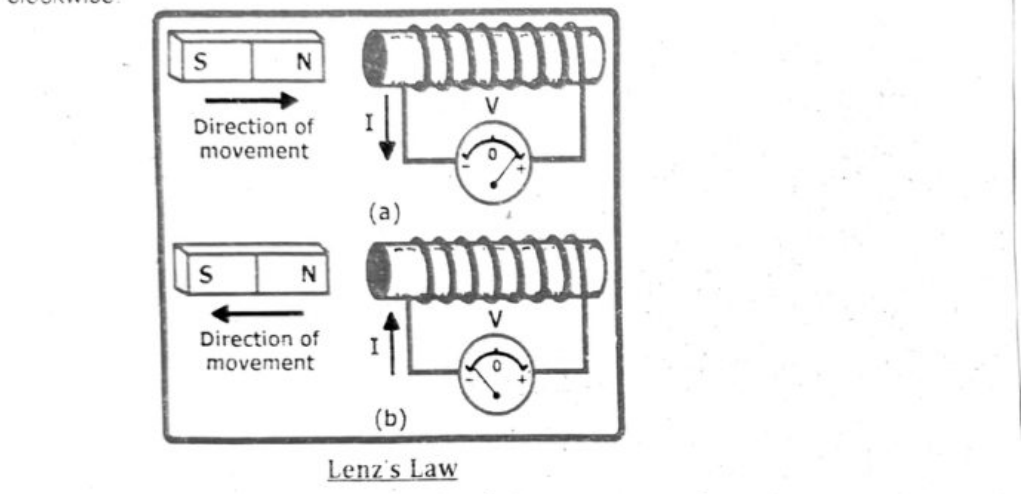
- The direction of the induced current in the coil by the induced (e.m.f) will be such that it will repel the north pole of the magnet. This is only possible if the left end of the solenoid becomes a north pole. Hence, according to right hand grip rule, the direction of the induced current in the coil will be anti clockwise.
Similarly, when we move the north pole of the magnet away from the coil. The direction of the induced current will be clockwise. In this case, left end of coil becomes South Pole. Hence in both the cases, the direction of induced current generates a magnetic field that oppose the motion of the bar magnet.
Working of alternating current (AC) generator:
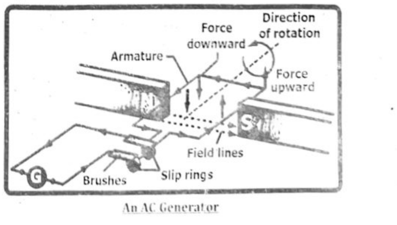
An AC generator converts mechanical energy into electrical energy through electromagnetic induction. It works by rotating a coil of wire within a magnetic field, inducing an alternating current (AC) in the coil. Slip rings and brushes are used to maintain a continuous connection to the external circuit as the coil rotates.
Principle of alternating current (AC) generator:
An AC generator or alternator, converts mechanical energy into electrical energy using the principle of electromagnetic induction, specifically Faraday’s Law.
Detailed explanation:
Magnetic Field:
The generator utilizes a strong magnetic field, often created by permanent magnets or electromagnets.
Rotating Coil (Armature):
A coil of wire, also known as the armature, is placed within this magnetic field.
Mechanical Rotation:
External mechanical force, like from a turbine, rotates the coil.
Electromagnetic Induction:
As the coil rotates, it cuts through the magnetic field lines, which induces a voltage (electromotive force or e. m. f) across the coil. This is based on Faraday’s law of induction.
Alternating Current (AC):
The direction of the induced voltage changes as the coil rotates, creating an alternating current in the coil and the external circuit.
Slip Rings and Brushes:
Two slip rings are connected to the ends of the rotating coil. Brushes, typically made of carbon, press against the slip rings, providing a sliding electrical contact. This allows the current to flow from the rotating coil to the external circuit without the need for wires to twist and tangle.
In essence, the rotating coil creates a changing magnetic flux, which induces an (e. m. f) and drives the flow of alternating current in the circuit.
Examples:
Simple Generator:
A rotating coil in a magnetic field experiences a changing magnetic flux due to the changing orientation of the coil with respect to the magnetic field lines. This changing flux induces an (e. m. f) in the coil.
Transformer:
A transformer uses two coils (primary and secondary) wound around a common core. Changing the current in the primary coil creates a changing magnetic flux that induces a voltage in the secondary coil. The ratio of the number of turns in the primary and secondary coils determines the voltage transformation ratio.
Solving Problems to Find the Magnitude of an Induced (e. m. f):
(i) PROBLEM 1:
Suppose a coil with 50 turns has a magnetic flux of 0.02 Weber (Wb) passing through it. If the magnetic flux changes to 0.05 Wb in 0.01 seconds, what is the magnitude of the induced (e. m. f)?
Solution:
Identify the given values:
Number of turns = (N) = 50
Initial magnetic flux = (Φ₁) = 0.02 Wb
Final magnetic flux = (Φ₂) = 0.05 Wb
Change in time = (Δt) = 0.01 s
Calculate the change in magnetic flux:
ΔΦ = Φ₂ − Φ₁ = 0.05 Wb − 0.02 Wb = 0.03 Wb
Apply Faraday’s Law to find the induced (e. m. f):
ε = −N × (ΔΦ / Δt)
ε = −50 × (0.03 Wb / 0.01 s)
ε = −150 volts
Determine the magnitude of the induced (e. m. f):
|ε| = |−150 V| = 150 V
Therefore, the magnitude of the induced (e. m. f) is 150 V.
(ii) PROBLEM 2:
A coil with 100 turns is placed in a uniform magnetic field. The magnetic flux through the coil changes uniformly from 0.05 Weber to 0 Weber in 0.01 seconds. Find the magnitude of the induced (e. m. f) in the coil.
Solution:
Identify the given values:
Number of turns = (N) = 100
Initial magnetic flux = (Φ₁) = 0.05 Wb
Final magnetic flux = (Φ₂) = 0 Wb
Time interval = (Δt) = 0.01 s
Calculate the change in magnetic flux:
ΔΦ = Φ₂ − Φ₁ = 0 Wb − 0.05 Wb = −0.05 Wb
Apply Faraday’s Law to find the induced (e. m. f):
Induced (e. m. f) = |N ΔΦ / Δt|
Induced (e. m. f) = |100 × (−0.05) / 0.01| = |−5 / 0.01| = |−500| = 500 Volts
Therefore, the magnitude of the induced (e. m. f) is 500 Volts.
LENZ’S LAW:
Lenz's law states that the direction of an induced electromotive force (e. m. f) and the resulting current is such that it opposes the change in magnetic flux that produced it. In simpler terms, the induced current will create a magnetic field that works against the change in the original magnetic field that caused the induced current. This opposition is a consequence of the law of conservation of energy.
Induced (e. m. f) and Current:
When a magnetic field changes near a conductor, it induces an electromotive force (e. m. f) in the conductor, which in turn drives a current.
Opposition:
Lenz’s law dictates that the direction of this induced current will be such that the magnetic field it creates opposes the change in the original magnetic field.
Example:
If you move a magnet towards a coil, the induced current in the coil will create a magnetic field that repels the approaching magnet. Conversely, if you move the magnet away from the coil, the induced current will create a magnetic field that attracts the receding magnet.
Conservation of Energy:
This opposition is not arbitrary: it's a manifestation of the principle of conservation of energy. The work done against the opposing force (induced magnetic field) is converted into electrical energy in the form of the induced current. If the induced current were to reinforce the change instead of opposing it, it would lead to a situation where energy is created from nothing, violating the law of conservation of energy.
- In essence, Lenz’s law helps us understand the direction of induced currents and is a fundamental principle in electromagnetism.
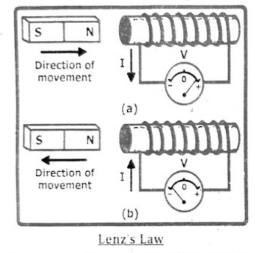
- The direction of the induced current in the coil by the induced (e. m. f) will be such that it will repel the north pole of the magnet. This is only possible if the left end of the solenoid becomes a north pole. Hence, according to right hand grip rule, the direction of the induced current in the coil will be anti clockwise.
Similarly, when we move the north pole of the magnet away from the coil. The direction of the induced current will be clockwise. In this case, left end of coil becomes South Pole. Hence in both the cases, the direction of induced current generates a magnetic field that oppose the motion of the bar magnet.
Working of alternating current (AC) generator:
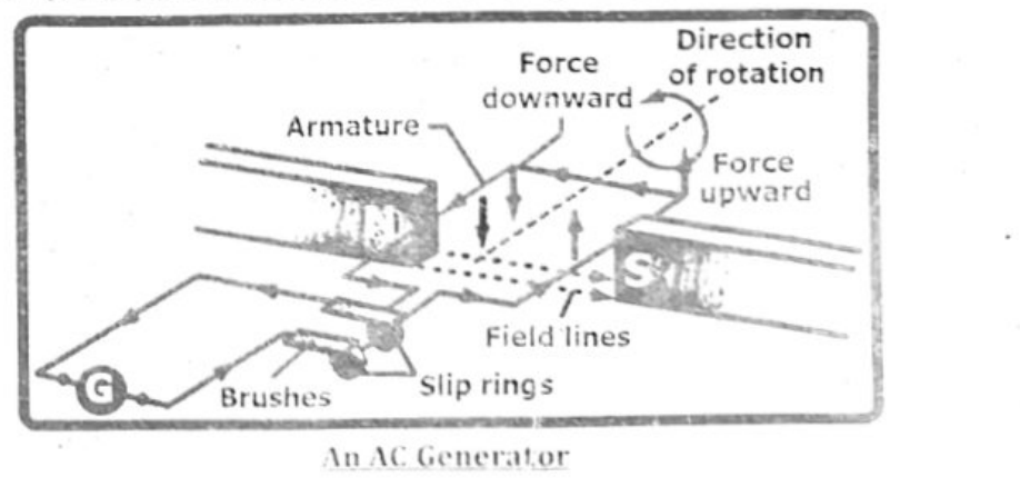
An AC generator converts mechanical energy into electrical energy through electromagnetic induction. It works by rotating a coil of wire within a magnetic field, inducing an alternating current (AC) in the coil. Slip rings and brushes are used to maintain a continuous connection to the external circuit as the coil rotates.
Principle of alternating current (AC) generator:
An AC generator or alternator, converts mechanical energy into electrical energy using the principle of electromagnetic induction, specifically Faraday’s Law.
Detailed explanation:
Magnetic Field:
The generator utilizes a strong magnetic field, often created by permanent magnets or electromagnets.
Rotating Coil (Armature):
A coil of wire, also known as the armature, is placed within this magnetic field.
Mechanical Rotation:
External mechanical force, like from a turbine, rotates the coil.
Electromagnetic Induction:
As the coil rotates, it cuts through the magnetic field lines, which induces a voltage (electromotive force or e. m. f) across the coil. This is based on Faraday’s law of induction.
Alternating Current (AC):
The direction of the induced voltage changes as the coil rotates, creating an alternating current in the coil and the external circuit.
Slip Rings and Brushes:
Two slip rings are connected to the ends of the rotating coil. Brushes, typically made of carbon, press against the slip rings, providing a sliding electrical contact. This allows the current to flow from the rotating coil to the external circuit without the need for wires to twist and tangle.
In essence, the rotating coil creates a changing magnetic flux, which induces an (e. m. f) and drives the flow of alternating current in the circuit.
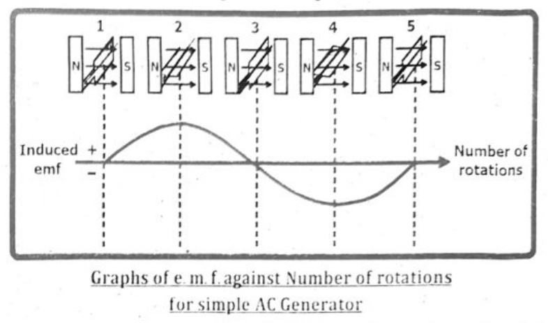
GRAPHS OF (e. m. f) AGAINST TIME FOR SIMPLE AC GENERATOR:
In a simple AC generator, the graph of (e. m. f) (electromotive force) against time is a sinusoidal wave, representing alternating current. The peaks of the graph correspond to when the coil is perpendicular to the magnetic field and the rate of change of magnetic flux is maximum, while the troughs represent the opposite, when the coil is perpendicular but the current is flowing in the opposite direction. The (e. m. f) is zero when the coil is parallel to the magnetic field (or when the magnetic flux is not changing).
Detailed Explanation:
(e. m. f) and Magnetic Flux:
An AC generator works by rotating a coil of wire within a magnetic field. The changing magnetic flux through the coil induces an e. m. f (voltage) in the coil.
Sinusoidal Wave:
The (e. m. f) generated varies sinusoidally with time, meaning it follows a wave pattern that repeats itself. This is because the magnetic flux through the coil changes sinusoidally as the coil rotates.
Peaks (Maximum e. m. f):
The peaks of the sinusoidal wave represent the maximum (e. m. f) generated by the coil. This occurs when the coil's plane is perpendicular to the magnetic field. In this position, the rate of change of magnetic flux through the coil is at its highest, leading to a maximum induced (e. m. f).
Troughs (Minimum e. m. f):
The troughs of the wave represent the minimum (e. m. f) generated by the coil. This occurs when the coil is still perpendicular to the magnetic field, but the direction of the induced current is reversed.
Zeros (Zero e. m. f):
The points where the sinusoidal wave crosses the time axis (zero e. m. f) correspond to the coil being parallel to the magnetic field. At this point, the magnetic flux through the coil is not changing, so there is no induced (e. m. f).
Relating Coil Position to (e. m. f):
Horizontal Position (Perpendicular to Field):
When the coil is horizontal, the magnetic flux through it is maximum, and the (e. m. f) is at its peak or trough (depending on the direction of rotation).
Vertical Position (Parallel to Field):
When the coil is vertical, the magnetic flux through it is zero, and the (e. m. f) is also zero.
Direction of Current:
The direction of the induced current changes with the direction of the magnetic flux change, resulting in alternating current.
The diagram shows how the (e. m. f) of the generator varies as its coil is rotated clockwise. Thus the (e. m. f) change smoothly from zero to some maximum values and back to zero during each half-turn of the loop. Basically, you can see that the output is alternating; it is a maximum when the coil is horizontal and zero when the coil is vertical.
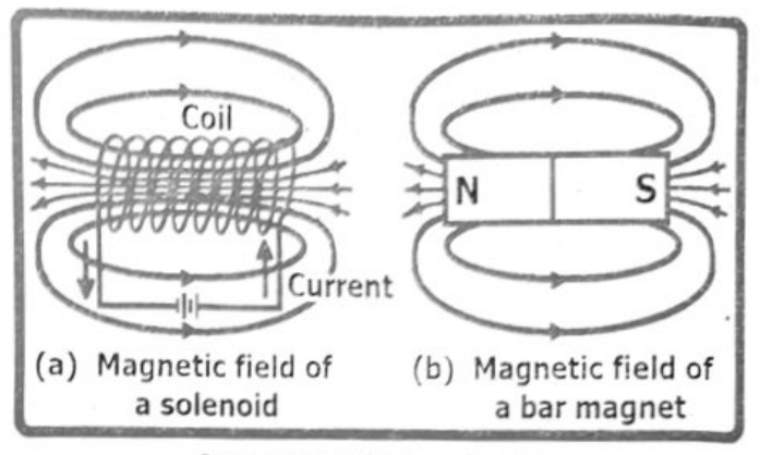
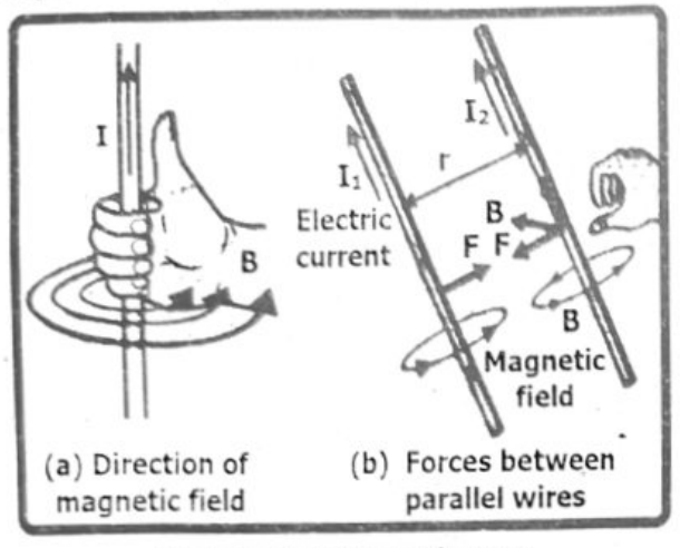
The magnetic field around a current-carrying straight wire is circular, with the field lines forming concentric circles around the wire. The direction of the magnetic field is determined by the right-hand rule: if you point your thumb in the direction of the current, your fingers curl in the direction of the magnetic field lines. For a solenoid, the magnetic field pattern is similar to that of a bar magnet, with a strong, uniform field inside the solenoid and field lines exiting the north pole and entering the south pole.
Straight Wire:
Pattern:
The magnetic field lines form concentric circles around the wire.
Direction:
The direction of the magnetic field can be determined using the right-hand rule. If you point your thumb in the direction of the current, your fingers curl in the direction of the magnetic field lines.
Strength:
The magnetic field strength decreases as you move away from the wire.
Current carrying conductors
Solenoid:
Polarity:
The north and south poles of the solenoid can be determined by the direction of the current flow and the direction of the winding (clockwise or counter-clockwise).
Strength:
The magnetic field strength increases with the number of turns in the solenoid and the amount of current flowing through it.
If we increase the magnitude of current the magnetic field will become stronger
Current carrying conductors
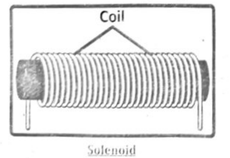
When a current-carrying solenoid is brought close to a suspended bar magnet, one end of the solenoid repels the north pole of the bar magnet. Thus, the current carrying solenoid has a north and a south pole and behaves like a permanent bar magnet. The direction of the magnetic field produced by a solenoid can be found with the help of right-hand rule as shown in figure. According to this rule if we grip the coil with our right hand by curling our fingers in the direction of the conventional current, our thumb will indicate the north pole of the coil, which is along the axis of the solenoid.
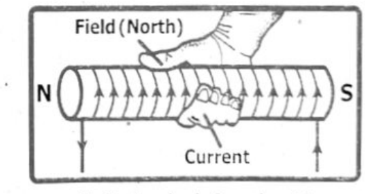
Changing the magnitude of the current in a conductor changes the strength of the magnetic field: increasing the current increases the field strength, while decreasing the current decreases the field strength. Reversing the direction of the current reverses the direction (polarity) of the magnetic field.
Elaboration:
Effect of Changing Current Magnitude:
The magnetic field's strength is directly proportional to the current flowing through a conductor. This means that if you double the current, you double the magnetic field strength at any given point around the conductor. Conversely, if you halve the current, the magnetic field strength is halved.
Effect of Changing Current Direction:
The direction of the magnetic field is determined by the direction of the current flow. A simple rule to visualize this is the right-hand grip rule: if you point your thumb in the direction of the current, your curled fingers indicate the direction of the magnetic field lines. Reversing the direction of the current will cause the magnetic field lines to reverse direction as well.
Right-Hand Rule:
The relationship between current direction and magnetic field direction can be visualized using the right-hand rule: if you point your thumb in the direction of the current, your fingers curl in the direction of the magnetic field lines.
In both relays and loudspeakers, the magnetic effect of a current is utilized to create motion or control circuits. In relays, a current-carrying coil creates a magnetic field that attracts a movable armature, which then opens or closes a switch to control another circuit. In loudspeakers, the interaction between a current-carrying coil and a permanent magnet creates a force that moves a diaphragm (cone), producing sound waves.
Relays:
- A relay uses an electromagnet to control a separate electrical circuit.
- When a small current flows through the electromagnet's coil, it creates a magnetic field.
- This magnetic field attracts a movable armature, which is connected to a switch.
- The movement of the armature either closes or opens the switch in the second circuit, effectively controlling a high-power circuit with a low-power signal.
- This allows a small signal to control a larger load or a circuit that operates at a different voltage or current.
Examples of Applications of relays:
Automotive:
Relays are widely used in cars to control high-current circuits like the starter motor, headlights, and fuel pump, using a low-current signal from the ignition switch or other control circuits.
Industrial Controls:
Relays are essential components in industrial machinery and control systems, enabling a low-voltage signal to control motors, heaters, and other high-power equipment.
Home Appliances:
Relays are used in various household appliances like washing machines, ovens, and air conditioners to switch on / off heating elements, motors, and other components based on signals from thermostats or timers.
Telecommunications:
Relays play a role in telephone switching systems and other communication networks to route signals and control connections.
Safety Systems:
Relays are used in safety circuits to quickly shut down equipment in case of a fault or emergency, such as in fire alarm systems or emergency stop circuits.
Loudspeakers:
- Loudspeakers use the force generated by the interaction of a current-carrying coil and a permanent magnet to produce sound.
- A coil of wire is placed within the magnetic field of a permanent magnet.
- When an electrical signal (alternating current) flows through the coil, it creates a magnetic field around the coil.
- This magnetic field interacts with the permanent magnet's field, creating a force on the coil.
- The force causes the coil to move back and forth, and since the coil is attached to a diaphragm (cone), the cone also moves.
- The movement of the cone creates vibrations in the air, which are perceived as sound waves.
- The frequency and amplitude of the electrical signal determine the frequency and amplitude of the sound produced.
Examples of Application of Loudspeakers:
This principle is fundamental to all dynamic loudspeakers, whether in headphones, home stereo systems, or public address systems.
An experiment to demonstrate the force on a current-carrying conductor in a magnetic field involves suspending a wire between the poles of a magnet and observing its movement when current flows through it. Reversing the current or the magnetic field direction will reverse the direction of the force.
Materials:
- A strong horseshoe magnet (or U-shaped magnet)
- A conducting wire (aluminum or copper)
- A battery or power supply
- Connecting wires
- Switch
- Stand to suspend the wire
- (Optional) A rheostat to control current
Procedure:
Setup:
Suspend the wire horizontally between the poles of the magnet, ensuring it is perpendicular to the magnetic field lines.
Current Flow:
Close the circuit by switching on the power supply. Observe the wire. It should be displaced (move) due to the force exerted on it by the magnetic field.
Reversing Current:
Reverse the direction of current flow through the wire by switching the terminals of the battery or power supply. Observe the direction of the wire's movement. It should now be in the opposite direction.
Reversing Magnetic Field:
If possible, reverse the poles of the magnet (or use a magnet with reversed polarity). Observe the wire's movement. It should again be reversed compared to its initial direction.
Explanation:
- The current flowing through the wire creates a magnetic field around it. This magnetic field interacts with the external magnetic field from the magnet, resulting in a force on the wire.
- The direction of this force is determined by Fleming's left-hand rule, where the thumb, index finger, and middle finger are held mutually perpendicular, with the index finger pointing in the direction of the magnetic field, the middle finger in the direction of the current, and the thumb indicating the direction of the force.
- Reversing the current or the magnetic field changes the direction of the force, causing the wire to move in the opposite direction.
Fleming’s left hand rule:
The relationship between the directions of force, magnetic field, and current in a conductor can be determined using the right-hand rule. If you point your thumb in the direction of the current and your fingers in the direction of the magnetic field, your palm will face the direction of the magnetic force on the conductor.
Detailed breakdown:
Current (I):
Represented by your thumb. It indicates the direction of positive charge flow (or the opposite direction of electron flow) in the conductor.
Magnetic Field (B):
Represented by your fingers. It points from the north pole to the south pole of the magnet.
Force (F):
Represented by your palm. It indicates the direction of the force exerted on the current-carrying conductor by the magnetic field.
The direction of the force on a current-carrying wire in a magnetic field is always perpendicular to that of the magnetic field and the current. It can be found by using Fleming’s left hand rule, as shown in figure.
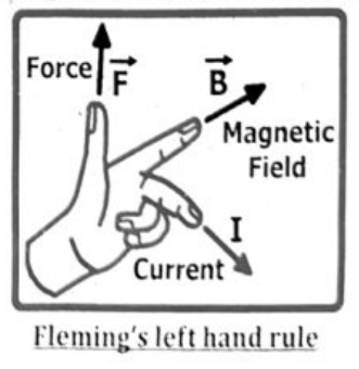
An experiment to demonstrate the force on a current-carrying conductor in a magnetic field involves suspending a wire between the poles of a magnet and observing its movement when current flows through it. Reversing the current or the magnetic field direction will reverse the direction of the force.
Materials:
- A strong horseshoe magnet (or U-shaped magnet)
- A conducting wire (aluminum or copper)
- A battery or power supply
- Connecting wires
- Switch
- Stand to suspend the wire
- (Optional) A rheostat to control current
Procedure:
Setup:
Suspend the wire horizontally between the poles of the magnet, ensuring it is perpendicular to the magnetic field lines.
Current Flow:
Close the circuit by switching on the power supply. Observe the wire. It should be displaced (move) due to the force exerted on it by the magnetic field.
Reversing Current:
Reverse the direction of current flow through the wire by switching the terminals of the battery or power supply. Observe the direction of the wire’s movement. It should now be in the opposite direction.
Reversing Magnetic Field:
If possible, reverse the poles of the magnet (or use a magnet with reversed polarity). Observe the wire’s movement. It should again be reversed compared to its initial direction.
Explanation:
- The current flowing through the wire creates a magnetic field around it. This magnetic field interacts with the external magnetic field from the magnet, resulting in a force on the wire.
- The direction of this force is determined by Fleming’s left-hand rule, where the thumb, index finger, and middle finger are held mutually perpendicular, with the index finger pointing in the direction of the magnetic field, the middle finger in the direction of the current, and the thumb indicating the direction of the force.
- Reversing the current or the magnetic field changes the direction of the force, causing the wire to move in the opposite direction.
Fleming’s left hand rule:
The relationship between the directions of force, magnetic field, and current in a conductor can be determined using the right-hand rule. If you point your thumb in the direction of the current and your fingers in the direction of the magnetic field, your palm will face the direction of the magnetic force on the conductor.
Detailed breakdown:
Current (I):
Represented by your thumb. It indicates the direction of positive charge flow (or the opposite direction of electron flow) in the conductor.
Magnetic Field (B):
Represented by your fingers. It points from the north pole to the south pole of the magnet.
Force (F):
Represented by your palm. It indicates the direction of the force exerted on the current-carrying conductor by the magnetic field.
The direction of the force on a current-carrying wire in a magnetic field is always perpendicular to that of the magnetic field and the current. It can be found by using Fleming’s left hand rule, as shown in figure.
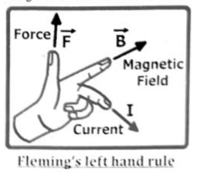
Fleming's left hand rule can be defined as:
Stretch the thumb, forefinger and the middle finger of the left hand mutually perpendicular to each other. If the forefinger points in the direction of the magnetic field, the middle finger in the direction of the current, then the thumb would indicate the direction of the force acting on the conductor.
Parallel current-carrying conductors create magnetic fields around them, and these fields interact to produce a force between the conductors. If the currents are in the same direction, the conductors attract each other; if the currents are in opposite directions, they repel. The force per unit length between two parallel conductors is proportional to the product of the currents and inversely proportional to the distance between them.
Magnetic Field Patterns:
- Same Direction Currents: When currents flow in the same direction in parallel wires, their magnetic fields combine between the wires, effectively canceling each other out, resulting in a net attraction.
- Opposite Direction Currents: When currents flow in opposite directions, their magnetic fields reinforce each other between the wires, causing a net repulsion.
Force on Conductors:
Attraction:
When currents are in the same direction, the magnetic forces between the conductors cause them to be pulled together.
Repulsion:
When currents are in opposite directions, the magnetic forces between the conductors cause them to be pushed apart.
Force Magnitude:
The force per unit length ($F/L$) between two parallel conductors is given by:
$$\frac{F}{L}=\frac{\mu_0 I_1 I_2}{2\pi r}$$
Where:
- $\mu_0$ is the permeability of free space (a constant).
- $I_1$ and $I_2$ are the magnitudes of the currents in the two conductors.
- $r$ is the distance between the conductors.
CURRENT CARRYING COIL IN A MAGNETIC FIELD:
A current-carrying coil in a magnetic field experiences a turning effect, and this turning effect is increased by increasing (a) the number of turns on the coil, (b) the current, and (c) the strength of the magnetic field.
$\tau = IBA\cos\alpha$
Explanation:
- Number of turns:
More turns on the coil means more wire is exposed to the magnetic field, resulting in a greater force and therefore a larger turning effect. - Current:
A higher current flowing through the coil creates a stronger magnetic field around it, leading to a greater turning effect. - Magnetic field strength:
A stronger magnetic field exerts a greater force on the current-carrying coil, increasing the turning effect. - Note:
If we increase the number of loops, the turning effect is greatly increased. This is the principle involved in electric motors.
- $\tau = IBA\cos\alpha$ — Where $\tau$ = torque
- $I$ = Current — $B$ = Magnetic field
- $A$ = Area of coil
- $\cos\alpha$ = The field makes an angle with the plane of coil
Hence we can say that, When a current-carrying loop is placed in a magnetic field, it experiences a couple due to which the coil begins to rotate. This is the working principle of electric motors.
The turning effect (or torque) is increased by increasing:
- the number of turns on the coil.
- the magnitude of the current passing through the loop.
- the strength of the magnetic field.
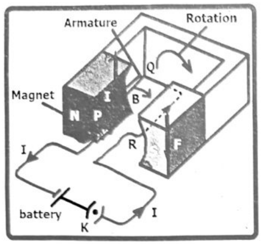
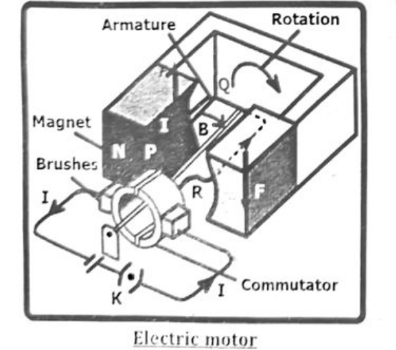
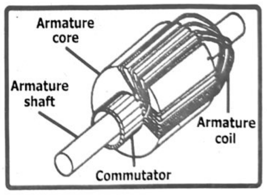
An electric motor converts electrical energy into mechanical energy, typically rotational motion, using the interaction of magnetic fields and electric currents. A split-ring commutator and brushes are essential components that enable the motor to rotate continuously by reversing the current direction in the coil every half turn.
Here's a breakdown of the process:
Magnetic Field:
A current-carrying coil is placed within a magnetic field, created by permanent magnets or electromagnets.
Force on the Coil:
When current flows through the coil, it experiences a force due to the interaction with the magnetic field. This force is determined by Fleming's Left-Hand Rule.
Torque and Rotation:
The forces on the coil's sides create a torque that causes the coil to rotate.
Split-Ring Commutator:
The split-ring commutator is a key component that reverses the direction of current flow in the coil every half-turn. It consists of a split ring divided into two halves, each connected to one end of the coil and rotating with it.
Brushes:
Brushes, typically made of carbon, are stationary contacts that press against the split-ring commutator. They provide a path for current to flow from the external circuit to the rotating coil and back.
Continuous Rotation:
By reversing the current direction every half-turn, the split-ring commutator ensures that the torque on the coil always acts in the same direction, resulting in continuous rotation. Without the commutator, the torque would reverse every half-turn, and the coil would oscillate rather than rotate continuously.
Working Mechanism:
As the coil rotates, the split-ring segments slide past the brushes. This switching action ensures that the current direction in the coil is reversed at the appropriate moment, maintaining the rotational force.
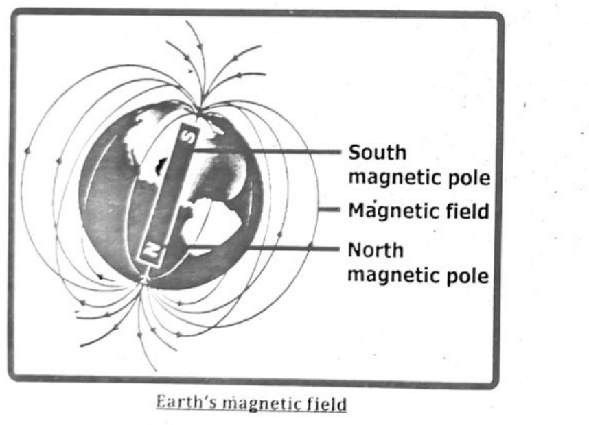
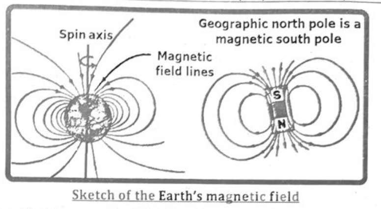
It’s theorized that the Earth’s magnetic field is generated by the “dynamo effect”, where the Earth’s rotation and its molten iron core, containing charged particles in motion, interact to produce a magnetic field. The Earth’s rotation creates kinetic energy, while heat sources within the core cause convection of the molten iron, which conducts electricity and generates electric currents. These currents then produce the magnetic field. It is theorized that the Earth’s magnetic field is generated by the dynamo effect, a process involving the movement of molten iron and nickel in the Earth’s outer core. This movement, driven by heat and the Earth’s rotation, creates electric currents, which in turn generate the magnetic field. This self-sustaining loop is known as the geodynamo.
The magnetic field lines are parallel to the surface of the Earth at the equator, and normal to the Earth’s surface at the magnetic poles.
The Earth’s magnetic field (also known as the geomagnetic field) is generated by the rotation of the Earth and its molten iron core that contains charged particles in motion. Core is primarily made up of the molten magnetic material such as iron and nickel. Molten iron is a good conductor. The movement of this molten iron, driven by convection currents and influenced by Earth’s rotation, creates electrical currents within the outer core. These currents produce a magnetic field, which maintains a stable and protective magnetic shield around the Earth. Earth’s magnetic field starts in the core of the Earth, coming out into space forming a magnetosphere.
A simple iron-cored transformer operates on the principle of electromagnetic induction. When an alternating current (AC) flows through the primary coil, it creates a changing magnetic field in the iron core. This changing magnetic field then induces a voltage in the secondary coil. Essentially, the transformer transfers electrical energy from one circuit to another through magnetic coupling, without a direct electrical connection.
Here’s a more detailed breakdown:
Primary Coil and Magnetic Field:
An alternating current is passed through the primary coil, which is wrapped around the iron core. This alternating current creates a fluctuating magnetic field around the primary coil.
Magnetic Core:
The iron core, being a ferromagnetic material, concentrates and channels the magnetic field lines, maximizing the magnetic flux linkage between the primary and secondary coils.
Secondary Coil and Induced Voltage:
The changing magnetic field generated by the primary coil then passes through the secondary coil. This changing magnetic flux induces an electromotive force (e.m.f.), which is essentially a voltage, in the secondary coil.
Voltage Transformation:
The ratio of the number of turns in the primary and secondary coils determines whether the transformer steps up (increases) or steps down (decreases) the voltage.
- Step-up transformer: If the secondary coil has more turns than the primary coil, the voltage is increased.
- Step-down transformer: If the secondary coil has fewer turns than the primary coil, the voltage is decreased.
$$\frac{V_s}{V_p}=\frac{N_s}{N_p}$$
This is the basic equation for transformer.
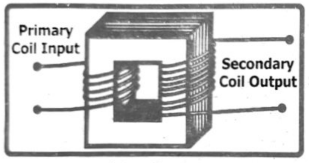
Transformer:
A transformer is an electrical device which is used to increase or decrease an AC voltage or current level.
Principle of Transformer:
The principle of transformer is mutual induction.
Construction of Transformer:
- Changing current (alternating current) in one coil induces e.m.f in another coil. The key components of the transformer are two coils or windings, electrically insulated from each other but wound on the same core. The core is typically made of a material which supports magnetism, such as soft iron.
- This makes almost these entire field lines pass through to the other winding, maximizing the mutual inductance of the two windings. The winding to which electric power is supplied is called the primary; the winding from which electric power is drawn is called the secondary.
Working of a transformer:
The transformer works on the principle of Faraday’s law of electromagnetic induction and mutual induction.
- There are usually two coils, primary coil and secondary coil, on the transformer core. The core laminations are joined in the form of strips. The two coils have high mutual inductance.
- When an alternating current pass through the primary coil it creates a varying magnetic flux. As per Faraday’s law of electromagnetic induction, this change in magnetic flux induces an e.m.f (electromotive force) in the secondary coil which is linked to the core having a primary coil. This is mutual induction.
Overall, a transformer carries the below operations:
- Transfer of electrical energy from circuit to another.
- Transfer of electrical power through electromagnetic induction.
- Electric power transfer without any change in frequency.
- Two circuits are linked with mutual induction.
Transformer Equation:
The transformer consists of an iron core on which two coils are wound: a primary coil with ‘$N_p$’ turns and a secondary coil with ‘$N_s$’ turns. If the voltage in the secondary is ‘$V_s$’ and voltage in primary is ‘$V_p$’, then:
$$\frac{V_s}{V_p}=\frac{N_s}{N_p}$$
Equation (1) is called Transformer Equation.
TYPES OF TRANSFORMER:
Step-Up Transformer:
If the secondary voltage is larger than the primary voltage, the transformer is called a step-up transformer.
If ‘$N_s$’ is greater than $N_p$ ($N_s > N_p$), the secondary (output) voltage ‘$V_s$’ is greater than the primary (input) voltage $V_p$ ($V_s > V_p$). In this case we have a step-up transformer.
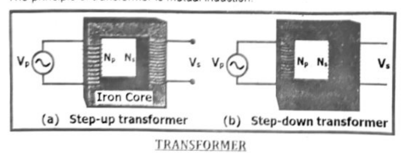
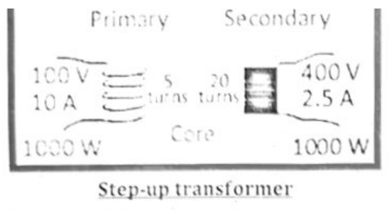
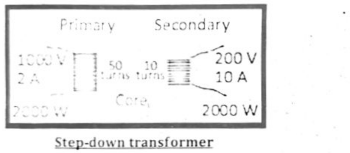
Step-Down Transformer:
If the secondary voltage is smaller than the primary voltage, the transformer is called a step-down transformer.
If ‘$N_s$’ is less than $N_p$ ($N_s < N_p$), then the secondary voltage ‘$V_s$’ is less than the primary voltage $V_p$ ($V_s < V_p$), and we have a step-down transformer. The ratio $N_s/N_p$ is referred to as the turns ratio of the transformer.
Ideal Transformer:
In an ideal transformer, the electric power delivered to the secondary circuit equals the power supplied to the primary circuit. An ideal transformer dissipates no power itself, and for such a transformer we can write:
$$P_p=P_s \quad\Rightarrow\quad V_p I_p=V_s I_s$$
A step-down transformer is installed in our streets which decrease the voltage to 220 volts
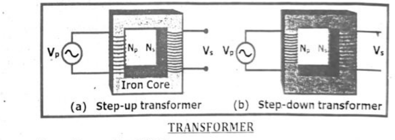
A step-up transformer increases voltage from the primary coil to the secondary coil, while a step-down transformer decreases voltage. The ratio of turns in the primary and secondary coils determines whether a transformer is step-up or step-down.
Here's a more detailed explanation:
Transformers utilize electromagnetic induction to transfer electrical energy between circuits. They consist of two coils of wire, the primary and secondary, wound around a common core (often iron).
- Primary Coil: This is the coil that receives the input AC voltage.
- Secondary Coil: This is the coil where the output voltage is induced.
Step-up Transformer:
In a step-up transformer, the secondary coil has more turns than the primary coil. This configuration increases the voltage from the primary to the secondary side. For example, if the primary coil has 100 turns and the secondary coil has 1000 turns, the voltage on the secondary side will be ten times higher than on the primary side, assuming a perfect transformer with no losses.
Step-down Transformer:
In a step-down transformer, the secondary coil has fewer turns than the primary coil. This configuration decreases the voltage from the primary to the secondary side. For example, if the primary coil has 1000 turns and the secondary coil has 100 turns, the voltage on the secondary side will be one-tenth of the voltage on the primary side.
Transformer Equation:
The transformer consists of an iron core on which two coils are wound: a primary coil with ‘$N_p$’ turns and a secondary coil with ‘$N_s$’ turns. If the voltage in the secondary is ‘$V_s$’ and voltage in primary is ‘$V_p$’, then
$$\frac{V_s}{V_p}=\frac{N_s}{N_p} \qquad (1)$$
Equation (1) is called Transformer Equation.
- Key Principle: The voltage transformation ratio is directly proportional to the ratio of the number of turns in the secondary coil to the number of turns in the primary coil.
- Power Consideration: While voltage is transformed, the power in the primary and secondary circuits of an ideal transformer is equal (assuming no energy losses). This means that if the voltage is stepped up, the current will be stepped down proportionally, and vice versa.
IDEAL TRANSFORMER:
In an ideal transformer, the electric power delivered to the secondary circuit is equal to the power supplied to the primary circuit. An ideal transformer dissipates no power itself, and for such a transformer, we can write:
Power in primary = Power in secondary or $I_sV_s=I_pV_p$
Transformer Equation:
The transformer consists of an iron core on which two coils are wound: a primary coil with ‘$N_p$’ turns and a secondary coil with ‘$N_s$’ turns. If the voltage in the secondary is ‘$V_s$’ and voltage in primary is ‘$V_p$’ then:
$$\frac{V_s}{V_p}=\frac{N_s}{N_p} \qquad (1)$$
Equation (1) is called Transformer Equation.
Solved Problems:
(i) PROBLEM 1:
The number of primary and secondary windings is 60 and 100 respectively. The secondary voltage is given by 250 V, determine the primary voltage.
Solution:
Given: $N_p=60$; $N_s=100$; $V_s=250\text{ V}$
The transformer formula is given by:
$V_p/V_s=N_p/N_s$
$V_p=N_p/N_s \times V_s=60/100 \times 250$
$V_p=150\text{ V}$
(ii) PROBLEM 2:
The number of primary and secondary windings is 110 and 240 respectively. The primary voltage is given by 300 V, which determines the secondary voltage.
Solution:
Given: $N_p=110$; $N_s=240$; $V_p=300\text{ V}$
The transformer formula is given by:
$V_p/V_s=N_p/N_s$
$V_s=N_s/N_p \times V_p=240/110 \times 300$
$V_s=654.5\text{ V}$
High-voltage transmission offers significant advantages in terms of efficiency and cost-effectiveness for long-distance power delivery. By transmitting electricity at higher voltages, the current required to deliver the same amount of power is reduced, leading to lower resistive losses in the transmission lines. This translates to less energy wasted as heat and a more efficient overall system. Furthermore, lower currents allow for the use of smaller, lighter, and more cost-effective conductors, reducing infrastructure costs.
Here’s a more detailed breakdown of the benefits:
Reduced Power Losses:
The primary advantage is the minimization of energy loss during transmission. Power loss in a conductor is proportional to the square of the current ($I^2Rt$). By using high voltage, the current is significantly reduced, thus minimizing these losses.
Smaller, Lighter Conductors:
Lower currents mean that smaller diameter and lighter conductors can be used for transmission lines. This reduces the material cost and simplifies the construction of transmission towers, which don’t need to support as much weight.
Increased Power Transfer Capability:
High-voltage transmission allows for the transfer of more power over longer distances with fewer losses. This is particularly important for connecting remote power generation sources to load centers.
Cost Savings:
The combination of reduced power losses and the ability to use smaller conductors leads to significant cost savings in both materials and infrastructure.
Improved Voltage Regulation:
Higher voltage levels lead to better voltage regulation at the receiving end, meaning a more stable and reliable power supply.
Compact Equipment Design:
The use of high voltage allows for smaller transformers and other equipment which can be beneficial in space-constrained environments. Therefore, using higher voltages for transmission allows for smaller currents, leading to reduced power losses in the cables. This is why power transmission lines operate at very high voltages.
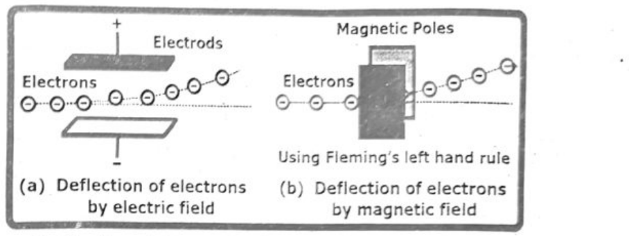
Electron beams can be deflected by both electric and magnetic fields. In an electric field, electrons, being negatively charged, are attracted to the positive plate and repelled by the negative plate, causing a parabolic deflection. In a magnetic field, electrons experience the Lorentz force, which is perpendicular to both their velocity and the magnetic field direction, resulting in circular or helical motion.
Deflection by Electric Fields:
Mechanism: When an electron beam enters an electric field, it experiences a force due to the field’s electric potential, causing it to accelerate towards the positively charged region and away from the negatively charged region.
Path: The deflection in an electric field is parabolic, as the force is constant and in one direction.
Example: In a cathode ray tube, electric fields are used to deflect the electron beam onto the screen, allowing for image display.
Deflection by Magnetic Fields:
Mechanism: Electrons moving in a magnetic field experience the Lorentz force, which is perpendicular to both their velocity and the magnetic field direction.
Path: If the magnetic field is uniform, the electron will follow a circular path, with the magnetic force acting as the centripetal force. If the magnetic field is not uniform, the electron may follow a helical path.
Example: Magnetic fields are used in electron microscopes to focus and deflect the electron beam, enabling high-resolution imaging.
Key Differences:
Kinetic Energy: In an electric field, the electron’s speed and kinetic energy change due to the force acting along the direction of motion. In a magnetic field, the magnetic force is always perpendicular to the velocity, so it only changes the direction of motion, not the speed or kinetic energy.
Nature of Deflection: Electric fields cause a parabolic deflection, while magnetic fields can cause circular or helical deflection depending on the field configuration.
Applications:
Electric fields are commonly used for controlling the position of electron beams, while magnetic fields are used for focusing and steering them in various applications.
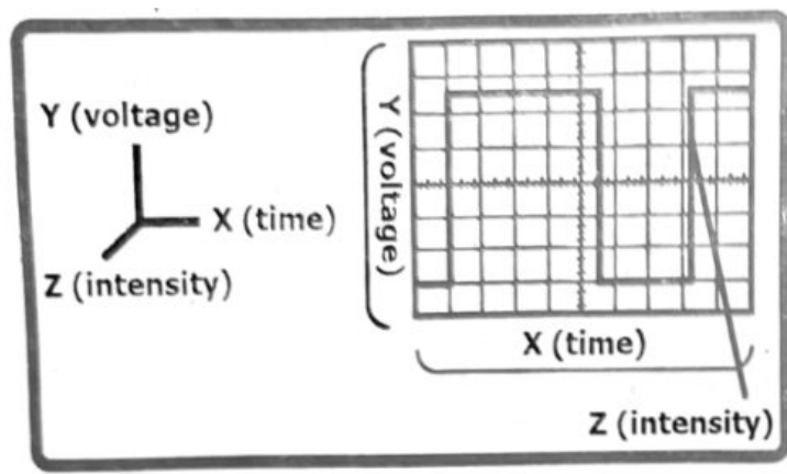
Interpreting oscilloscope waveforms involves analyzing their shape, amplitude, and time characteristics to understand the behavior of electrical signals. Key aspects include identifying the waveform’s shape (sine, square, etc.), measuring voltage levels (amplitude) and timing (period, frequency) using the oscilloscope’s controls, and detecting any distortions or anomalies.
Key Elements of Waveform Interpretation:
Amplitude:
The vertical axis of the waveform represents voltage. By observing the height of the waveform, you can determine the voltage level (e.g. peak-to-peak voltage).
Time:
The horizontal axis represents time. You can measure the duration of a cycle (period) or the time it takes for a signal to change (rise time, fall time).
Waveform Shape:
The shape of the waveform (sine, square, triangle, etc.) reveals the type of signal and its characteristics. For example, a sine wave indicates a smooth, oscillating signal, while a square wave suggests a digital signal.
Distortion:
Deviations from the ideal waveform shape can indicate problems like noise, ringing, or other signal imperfections.
Analyzing Waveform Characteristics:
Amplitude Measurements:
Use the oscilloscope's cursors or automatic measurement functions to determine voltage levels at specific points on the waveform.
Time Measurements:
Determine the period, frequency, rise time, and fall time of the waveform.
Waveform Shape Analysis:
Identify the type of waveform and look for any deviations from the expected shape.
Anomaly Detection:
Examine the waveform for any unusual spikes, glitches, or distortions that might indicate a problem.
Signal Averaging and Filtering:
For noisy signals, consider using signal averaging or noise filtering techniques to improve clarity and make it easier to interpret the waveform.
Cathode Ray Oscilloscope (CRO):
The cathode ray oscilloscope (CRO) is a type of electrical instrument which converts electric signal to visual signal and is used for showing the measurement and analysis of waveforms and other electronic and electrical phenomenon.
Components of Cathode-Ray Oscilloscope (CRO):
The cathode-ray oscilloscope (CRO) consists of the following components:
- The electron gun
- The deflecting plats
- A fluorescent screen
Construction of Cathode Ray Oscilloscope (CRO):
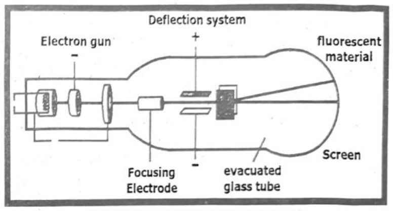
The block diagram of (CRO) is shown in the figure below, in which the accelerated electron beam from the electron gun is brought to the focal point on a fluorescent screen, with the help of focusing electrode. Thus, the screen produces a visible spot at center where the electron beam strikes it. The visible spot on the screen is observed because it is coated with a thin layer of phosphor (a material that gives light when electrons strike it).
The horizontal and vertical plates are placed between the focusing electrode and the screen, thus it can detect the beam according to the input signal. The deflector has two mechanisms, one to change the vertical direction and one to change the horizontal direction of the beam. This allows the electron beam to sweep over the entire screen.
Working Principle:
- Working principle of (CRO) depends on the electron ray movement because of the electrostatic force.
- Once an electron ray hits a phosphor face, then it makes a bright spot on it. A Cathode Ray Oscilloscope applies the electrostatic energy on the electron ray from two vertical ways.
- The spot on the phosphor monitor turns due to the effect of these two electrostatic forces which are mutually perpendicular. It moves to make the necessary waveform of the input signal.
Uses of Cathode Ray Oscilloscope (CRO):
Measurements of electrical quantities can be done by using (CRO).
For example,
- Measurement of Amplitude
- Measurement of Time Period
- Measurement of Frequency
It is used in laboratories for the purpose of research. Once researchers design a new circuit, they use (CRO) to verify the waveforms of voltage and
Examples:
Given:
Primary voltage $V_p = 240\text{ V}$
Secondary voltage $V_s = 12\text{ V}$
Turns in primary $N_p = 2000$
Required:
Turns in secondary $N_s = ?$
Solution:
The basic transformer equation is:
$$\frac{V_s}{V_p}=\frac{N_s}{N_p}$$
or
$$N_s=\frac{V_s}{V_p}\times N_p$$
Putting values:
$$N_s=\frac{12\text{ V}}{240\text{ V}}\times 2000$$
Therefore, $N_s=100$ [ANSWER]
The secondary coil should only have 100 turns compared to 2000 turn in the primary.
Summary
- Right-hand rule for current carrying wire is that the wire is grasped in fist of right hand with the thumb pointed in the direction of the current, the fingers of the hand will curl in the direction of magnetic field. This is the right-hand rule for current carrying wire.
- Two long parallel wires carrying a current in same direction attract each other.
- Right-hand rule for solenoid is that if we grip the coil with our right hand by curling our fingers in the direction of the conventional current, our thumb will indicate the north pole of the coil, which is along the axis of solenoid.
- The Earth’s magnetic field is generated by the rotation of the Earth and its molten iron core that contains charged particles in motion.
- Relay is an electrical control device that facilitates interaction between the input and output circuits.
- Current carrying conductor is placed in a magnetic field experiences a force.
- Fleming’s left hand rule is that stretch the thumb, forefinger, and the middle finger of the left hand mutually perpendicular to each other. If the forefinger points in the direction of the magnetic field, the middle finger in the direction of the current, then the thumb would indicate the direction of the force acting on the conductor.
- Working principle of electric motors is when a current-carrying loop is placed in a magnetic field, it experiences a couple due to which the coil begins to rotate.
- Electric motor is device that converts electric energy into mechanical energy.
- Electromagnetic induction is the production of an electromotive force across a conductor when it is exposed to a varying magnetic field.
- Lenz’s Law states that the direction of induced current in a circuit is always such that it opposes the cause which produces it.
- A.C generator converts mechanical energy into electrical energy.
- Transformer is an electrical device which is used to increase or decrease the value of an alternating voltage.
- Step-up transformer is used to increase the incoming voltage.
- Step-down transformer is used to decrease the incoming voltage.
- The waveform on oscilloscope can be controlled by applying electric field of suitable magnitude.