
QII. Follow the directions to respond to the following questions.
Constructed Response Questions:
Q1. In which direction the current must be flowing through the conductor to create the magnetic field shown in the diagram? Up or Down?
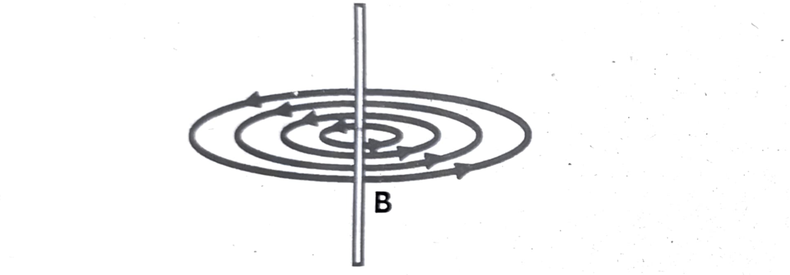
To create the magnetic field shown in the diagram, the current must be flowing upwards through the conductor.
Explanation:
Using the right-hand rule for a straight current-carrying conductor, if you point your thumb in the direction of the current (upwards in this case), your curled fingers will indicate the direction of the magnetic field lines, which in this scenario would be counterclockwise, as shown in the diagram.
Q2. In the following diagram, will there be a North pole or a South pole at the left side of the solenoid? Also draw its magnetic field having arrows to show its direction.
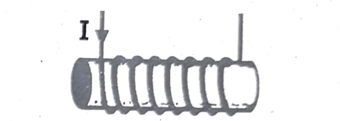
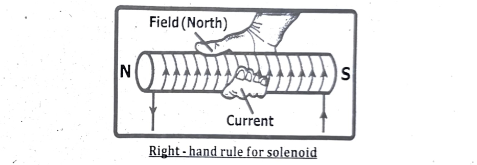
- If the current is flowing counterclockwise when viewed from the left side of the solenoid, then the left side will be the North pole. If the current is flowing clockwise when viewed from the left, then the left side will be the South pole.
- The magnetic field lines will point from the North pole (left side in the first case) to the South pole (right side) both inside and outside the solenoid.
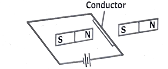
Q3. A current carrying conductor is place in the magnetic field, as shown.
- In which direction will the conductor move? Up, down, left or right?
- If the magnetic field was reversed then in which direction will the conductor move?
Answers
a) In which direction will the conductor move? Up, down, left, or right?
The conductor will move upward in this scenario. This is determined by applying Fleming’s left-hand rule, which states that if you point your index finger in the direction of the magnetic field and your middle finger in the direction of the current, your thumb will point in the direction of the force, and thus the motion of the conductor.
b) If the magnetic field was reversed, then in which direction will the conductor move?
The conductor will move downward in this scenario. If the magnetic field is reversed, the conductor will move in the opposite direction compared to its original motion. Reversing the magnetic field effectively reverses the direction of the force, causing the conductor to move in the opposite direction.
c) If both the magnetic field and the current are reversed, then in which direction will the conductor move?
The conductor will move upward in this scenario. If both the magnetic field and the current are reversed, the conductor will move in the same direction as it would have moved with the original magnetic field and current.
Short Questions:
Q1. How does a generator differ from a motor, and what is their relationship to each other?
A motor converts electrical energy into mechanical energy, while a generator converts mechanical energy into electrical energy. Essentially, a motor uses electricity to produce motion, whereas a generator uses motion to produce electricity.
Detailed Breakdown:
(i) Motor:
- Function: Converts electrical energy into mechanical energy, typically rotating a shaft.
- Input: Electrical energy (current).
- Output: Mechanical energy (rotational force or torque).
- How it works: A motor utilizes the interaction between magnetic fields and current-carrying conductors to produce force.
- Example: A fan motor, an electric car motor, a power drill motor.
(ii) Generator:
- Function: Converts mechanical energy into electrical energy.
- Input: Mechanical energy (e.g., from a spinning turbine, engine, or human power).
- Output: Electrical energy (current).
- How it works: A generator uses the principle of electromagnetic induction, where a moving conductor in a magnetic field generates a voltage and current.
- Example: A power plant generator, a bicycle generator (dynamo), a wind turbine generator.
Relationship between Generator and Motor:
- Reciprocal Devices: Generators and motors are often paired together in systems. For example, a generator can be used to power a motor, or a motor can be used to drive a generator.
- Complementary Roles: Generators are used to produce electricity, and motors are used to consume that electricity to perform work.
- Similarities: Both devices rely on the principles of electromagnetism, involving magnetic fields and electric currents. They often share similar physical components like magnetic poles, coils, and shafts.
- Reversibility: In some cases, a motor can be used as a generator, and vice versa, though they are typically designed for optimal performance in one role or the other.
Q2. Why is a transformer ineffective with DC voltage?
Transformers are ineffective with DC voltage because they rely on a changing magnetic field, which is produced by alternating current (AC), to induce a voltage in the secondary coil. DC voltage provides a constant, unchanging current, and thus a constant magnetic field, which cannot induce a voltage in the secondary coil. In essence, transformers need a constantly changing magnetic field to function, which is provided by AC, not DC.
Q3. Explain the relationship between the direction of a current-carrying conductor and the magnetic field it produces.
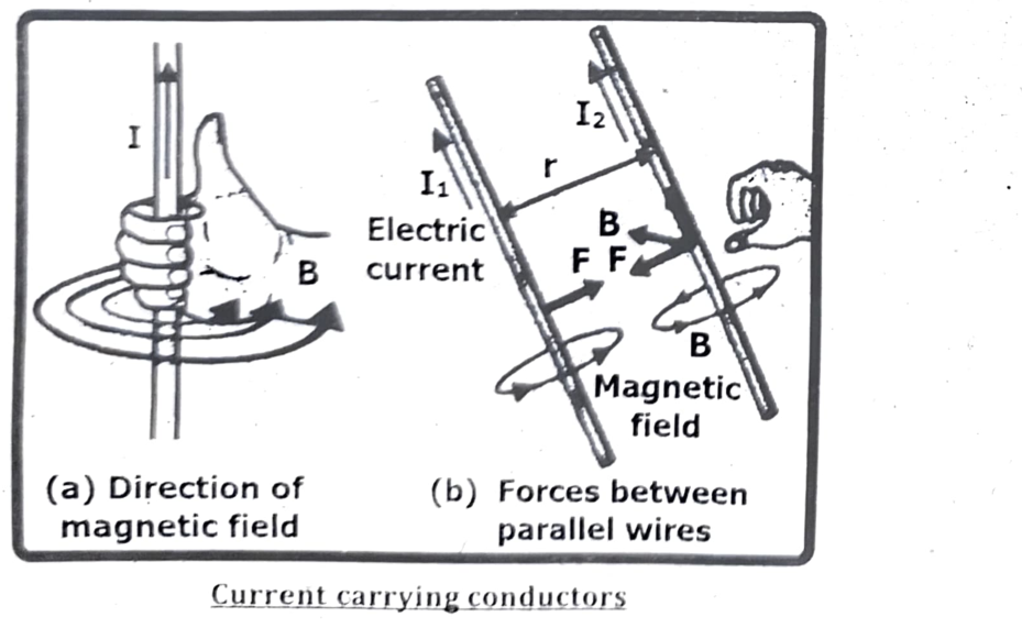
The magnetic field produced by a current-carrying conductor is always perpendicular to the direction of the current. Using the right-hand rule, you can visualize this relationship: if you point your thumb in the direction of the current flow, your fingers will curl in the direction of the magnetic field lines.
Elaboration:
- Right-Hand Rule: This rule is a handy tool for determining the direction of the magnetic field. Imagine holding the wire with your right hand, with your thumb pointing in the direction of the current. The way your fingers curl around the wire indicates the direction of the magnetic field lines.
- Circular Field: The magnetic field lines around a straight, current-carrying wire are circular, concentric circles centered on the wire.
- Perpendicular Relationship: The current flows along the length of the wire (a linear direction), while the magnetic field circles around it (a rotational direction). This demonstrates the perpendicular relationship between the two.
- Strength of the Field: The strength of the magnetic field is directly proportional to the current. A stronger current produces a stronger magnetic field. Additionally, the strength decreases as you move further away from the wire, according to a physics reference site.
- Parallel Conductors: If you have two parallel wires carrying current, the magnetic fields they produce will interact. If the currents are in the same direction, the wires will attract. If the currents are in opposite directions, the wires will repel.
Q4. Describe the interaction between a current-carrying conductor and a magnetic field, and how to determine the direction of the force exerted.
A current-carrying conductor placed in a magnetic field experiences a force. This force’s direction can be determined using Fleming’s left-hand rule or the right-hand rule for magnetic fields, where the thumb indicates the force direction, the index finger indicates the magnetic field direction, and the middle finger indicates the current direction.
Interaction:
- When a current flows through a conductor, it creates a magnetic field around it.
- If a magnet or another magnetic field source is brought near this current-carrying conductor, the two magnetic fields interact.
- This interaction results in a force being exerted on the conductor.
- The force is proportional to the current, the length of the conductor within the magnetic field, and the magnetic field strength, as described by the formula:
$F=ILB\sin\alpha$
Where:
- $F$ = Force
- $I$ = Current
- $L$ = Length of the conductor
- $B$ = Magnetic field
- $\sin\alpha$ = Angle between conductor and field
The force is perpendicular to both the direction of the current and the magnetic field.
Determining the Force Direction:
Fleming’s Left-Hand Rule:
- Stretch out your left hand with your index finger, middle finger, and thumb perpendicular to each other.
- Point your index finger in the direction of the magnetic field (from North to South).
- Point your middle finger in the direction of the current flow.
- Your thumb will then point in the direction of the force acting on the conductor.
Right-Hand Rule for Magnetic Fields (also called the right-hand grip rule):
- Imagine gripping the current-carrying wire with your right hand.
- Point your thumb in the direction of the current flow.
- Your curled fingers will then point in the direction of the magnetic field lines around the wire.
Q5. Why is high voltage used for long-distance transmission of electrical power?
High voltage is used for long-distance power transmission because it minimizes energy loss due to resistance in the transmission lines. By using high voltage, the current can be reduced for a given amount of power, and since power loss is proportional to the square of the current, lower currents lead to significantly less energy wasted as heat.
Here’s a more detailed explanation:
- Power and Voltage / Current Relationship: The amount of power transmitted is the product of voltage and current (Power = Voltage × Current).
- Power Loss ($I^2R$): The power lost in the transmission line due to resistance is proportional to the square of the current (Power Loss = Current$^2$ × Resistance).
$P_{loss}=I^2R$
Since the power loss is proportional to the square of the current ($I^2R$), reducing the current significantly reduces the energy lost as heat in the transmission lines.
- Minimizing Losses: To minimize power loss during transmission, it’s more efficient to transmit at high voltage and low current rather than low voltage and high current.
- Efficiency: Transmitting power at high voltage and low current greatly increases the efficiency of the power transmission system, allowing more of the generated power to reach its destination.
- Example: If you double the voltage, you can halve the current for the same amount of power. This results in a four-fold reduction in power loss (since power loss is proportional to current squared).
- Transformers: Power is generated at lower voltages. Transformers are used to step up the voltage for transmission and then step it down again at the receiving end for local distribution.
Q6. Design an experiment to generate an electric current using a coil of wire and a bar magnet.
Experiment:
Generating Electricity with a Coil and Magnet
Objective:
To demonstrate the generation of an electric current in a coil of wire using a bar magnet.
Materials:
- A coil of wire (insulated copper wire is best)
- A bar magnet
- A galvanometer (or a sensitive ammeter) to detect small currents
- Connecting wires
- (Optional) A multimeter to measure voltage
Procedure:
- Connect the Coil to the Galvanometer:
Connect the two ends of the coil of wire to the terminals of the galvanometer (or ammeter). Make sure the connections are secure.
- Observe the Galvanometer (Initial State):
With the magnet far away from the coil, observe the galvanometer. It should read zero, indicating no current is flowing in the circuit.
- Move the Magnet:
- Move the magnet towards the coil: Quickly push the North Pole of the bar magnet into the center of the coil. Observe the galvanometer. Note the direction and magnitude of the deflection.
- Hold the magnet stationary inside the coil: Once the magnet is inside the coil, hold it still. Observe the galvanometer. It should return to zero, indicating no current flow.
- Move the magnet away from the coil: Quickly pull the magnet out of the coil. Observe the galvanometer. Note the direction and magnitude of the deflection. It should deflect in the opposite direction compared to when you pushed the magnet in.
- Repeat with the South Pole: Repeat the above steps, but this time use the South pole of the magnet. Observe any differences in the direction of the current.
- Vary the Speed of Movement:
Repeat the experiment, varying the speed at which you move the magnet in and out of the coil. Observe how the speed affects the magnitude of the current (the deflection of the galvanometer).
- (Optional) Use a Multimeter:
If you have a multimeter, you can measure the voltage induced across the coil while moving the magnet.
Observations:
- Moving Magnet: You should observe that a current is induced in the coil only when the magnet is moving relative to the coil.
- Direction of Current: The direction of the induced current changes depending on whether the magnet is moving into or out of the coil, and on which pole (North or South) is used.
- Speed of Movement: The faster the magnet moves, the greater the induced current (larger deflection on the galvanometer).
Explanation:
- Electromagnetic Induction: This experiment demonstrates Faraday’s law of electromagnetic induction. When the magnet is moving relative to the coil, the magnetic field lines passing through the coil are changing. This changing magnetic field induces a voltage (electromotive force or e.m.f.) in the coil, which drives the current.
- Lenz’s Law: The direction of the induced current is such that it creates a magnetic field that opposes the change in the original magnetic field (Lenz’s Law). This is why the current direction reverses when the magnet is moved in versus out.
Conclusion:
This experiment demonstrates that a changing magnetic field can induce an electric current in a coil of wire. This is the fundamental principle behind electric generators.
Q7. What factors influence the strength of an induced electromotive force (e. m. f)?
The strength of an induced electromotive force (e. m. f) is influenced by several factors related to the magnetic field and the circuit. Specifically, the strength of the induced (e. m. f) is directly proportional to the rate of change of magnetic flux, the number of turns in the coil, and the strength of the magnetic field. Additionally, the area of the coil and the orientation of the coil relative to the magnetic field also play a role.
Here’s a more detailed breakdown:
- Rate of Change of Magnetic Flux:
The faster the magnetic field changes through a circuit, the greater the induced (e. m. f). This change can be achieved by moving a magnet, changing the magnetic field strength, or changing the area of the coil.
- Number of Turns in the Coil:
More turns in a coil mean a greater induced (e. m. f). Each turn contributes to the total magnetic flux, so increasing the number of turns multiplies the effect.
- Magnetic Field Strength:
A stronger magnetic field means a greater induced (e. m. f). A stronger magnet or a higher magnetic field density will result in a larger induced (e. m. f).
- Coil Area:
A larger coil area that intercepts the magnetic field will experience a greater induced (e. m. f).
- Orientation of the Coil:
The angle between the coil and the magnetic field lines also affects the induced (e.m.f). Maximum (e.m.f) is induced when the coil’s area is perpendicular to the magnetic field lines.
- Speed of Motion:
Moving the conductor faster through the magnetic field also increases the rate of change of magnetic flux, leading to a larger induced (e.m.f).
$$\text{e.m.f.}=\varepsilon=2NvBL\sin\theta$$
Where:
- ε = e.m.f.; N = Number of turns of coil
- v = Speed; B = Magnetic field; L = Length of coil
- Sin θ = angle between v and B
Q8. Compare and contrast the two primary types of transformers.
The two primary types of transformers are core type and shell type. Core type transformers have windings on two limbs of a rectangular core, while shell type transformers have windings on the central limb of a three-limbed core. Core type transformers are generally preferred for high-voltage, high-power applications, whereas shell type transformers are more suitable for low-voltage, low-power applications.
Core Type Transformers:
- Structure: Windings are placed on two limbs of a rectangular core.
- Magnetic Circuits: Has two magnetic circuits.
- Applications: Suitable for high-voltage and high-power applications.
- Cooling: Can be cooled by oil or air, with oil cooling being more common for larger units.
Shell Type Transformers:
- Structure: Windings are placed on the central limb of a three-limbed core.
- Magnetic Circuits: Has one magnetic circuit.
- Applications: More suitable for low-voltage and low-power applications.
- Cooling: Can be cooled by oil or air, with oil cooling being more common for larger units.
Q9. Identify three devices that operate on the principle of electromagnetic induction.
Three devices that operate on the principle of electromagnetic induction are electric generators, transformers, and electric motors.
Explanation:
- Electric Generators: Generators convert mechanical energy into electrical energy. They use the principle of electromagnetic induction where a rotating coil in a magnetic field induces an electric current.
- Transformers: Transformers are used to increase or decrease voltage in an alternating current (AC) circuit. They rely on electromagnetic induction between two coils of wire with different numbers of turns.
- Electric Motors: Motors convert electrical energy into mechanical energy. They use the interaction between magnetic fields and current-carrying conductors to produce rotational motion, which is based on electromagnetic induction.
Long Questions:
Q1. Design an experiment to qualitatively demonstrate the existence of a magnetic field around a current-carrying conductor.
To demonstrate the magnetic field around a current-carrying conductor, a simple experiment involves using a compass and a wire connected to a battery. When current flows through the wire, the compass needle will deflect, indicating the presence of a magnetic field. Reversing the current direction will reverse the compass needle’s deflection, further confirming the magnetic field’s connection to the current.
Materials:
- A battery (e.g., 1.5 V AA or AAA)
- Connecting wires
- A switch (optional, but helpful)
- A compass
- A straight, insulated copper wire (about 10–15 cm long)
Procedure:
- Set up the circuit:
Connect one end of the wire to one terminal of the battery (e.g., positive). Connect the other end of the wire to the switch, and then the switch to the other battery terminal (e.g., negative).
- Position the compass:
Place the compass near the middle of the wire, ensuring it’s not too close to the battery terminals or the switch, as these might introduce unwanted magnetic fields.
- Observe the compass needle:
With the switch open (no current), observe the compass needle’s alignment. It should point roughly north, as it normally does.
- Close the switch:
Close the switch to complete the circuit and allow current to flow through the wire. Observe the compass needle’s deflection. It should no longer point north but will deflect to the side, indicating the presence of a magnetic field.
- Reverse the current:
Open the switch and reverse the connections of the wire to the battery terminals. This will reverse the direction of current flow in the wire.
- Observe again:
Close the switch again and observe the compass needle’s deflection. It should now deflect in the opposite direction compared to the previous observation.
- Repeat:
You can repeat the process and vary the current by using a variable resistor (rheostat) or a different battery to observe the change in the strength of the magnetic field (i.e., the degree of deflection).
Explanation:
The deflection of the compass needle indicates the presence of a magnetic field. The direction of the deflection is determined by the direction of the current in the wire, according to the right-hand rule. This experiment demonstrates that a current-carrying conductor produces a magnetic field around it, and the field’s direction is related to the current’s direction.
Q2. Describe an experimental setup to induce an (e. m. f) in a circuit using a changing magnetic field. How can you measure the induced (e. m. f)?
To induce an electromotive force (e. m. f) in a circuit using a changing magnetic field, you can perform an experiment where a magnet is moved through a coil of wire. The changing magnetic flux through the coil induces an (e. m. f) which can be measured with a voltmeter or a data logger.
Here’s a detailed description of the setup and measurement:
Experimental Setup:
- Coil of Wire:
Use a coil of wire, preferably with many turns, connected to a sensitive voltmeter or a data logger.
- Magnet:
A bar magnet or a solenoid with a changing current can be used as the source of the magnetic field.
- Relative Motion:
The key is to create relative motion between the coil and the magnetic field. This can be achieved by:
- Moving the magnet in and out of the coil.
- Moving the coil over the magnet.
- Changing the current in a nearby electromagnet (this will change the magnetic field).
- Measuring the (e. m. f):
- Voltmeter: A sensitive voltmeter can be directly connected to the coil’s terminals to measure the induced (e. m. f).
- Data Logger: A data logger can record the voltage over time, allowing for a more detailed analysis of the (e. m. f)’s behavior.
Explanation:
- Faraday’s Law: The induced (e. m. f) is directly related to the rate of change of magnetic flux through the coil, according to Faraday’s Law:
$$\varepsilon=-N\frac{\Delta\Phi}{\Delta t}$$
Where:
$\varepsilon$ = induced voltage; $N$ = number of turns
$\Delta\Phi$ = change in magnetic flux; $\Delta t$ = change in time
- Changing Magnetic Flux: When the magnet moves, the magnetic field lines passing through the coil change, causing a change in magnetic flux.
- Induced (e. m. f): This change in magnetic flux induces an (e. m. f) in the coil, which drives a current if the circuit is complete.
- Direction of e. m. f. (Lenz’s Law): The direction of the induced (e. m. f) opposes the change in magnetic flux that produced it (Lenz’s Law).
Measuring the (e. m. f):
- Voltmeter:
The voltmeter will show a voltage reading when there is a change in magnetic flux through the coil. The magnitude of the reading will be proportional to the rate of change of flux.
- Data Logger:
The data logger will record voltage as a function of time, allowing you to see how the (e. m. f) changes as the magnet is moved or as the magnetic field changes. By analyzing the data, you can determine the relationship between the induced (e. m. f), the rate of change of magnetic flux, and the number of coil turns.
Q3. Explain Lenz’s law in your own words, and provide a real-world example to illustrate its application.
Lenz’s Law:
- Lenz’s law determines the direction of this induced current, which opposes the change in magnetic flux. For example, if a bar magnet moves downward, the induced magnetic field points upward, resulting in a counterclockwise current. Conversely, if a loop exits a magnetic field, the induced current is clockwise.
- Lenz’s law explains how induced currents oppose changes in magnetic flux. It’s crucial for understanding electromagnetic induction and energy conservation in magnetic systems. This law helps us grasp why induced currents flow in specific directions.
- Applications of Lenz’s law are everywhere, from magnetic brakes in trains to eddy currents in induction cooktops. These real-world examples show how this principle is used to control motion, generate heat, and create useful electromagnetic effects.
Applications of Lenz’s Law:
Magnetic Braking:
- Magnetic braking is an application of Lenz’s law used to slow down or stop moving objects.
- When a conductor moves through a magnetic field, an induced current is generated in the conductor according to Lenz’s law.
- The induced current creates a magnetic field that opposes the motion of the conductor, causing a braking effect.
Examples of magnetic braking include:
- Eddy current brakes in trains, which use electromagnets to induce currents in the train wheels, slowing them down.
- Electromagnetic brakes in vehicles, which use the same principle to slow down the wheels.
- Induction cooktops, which use magnetic fields to induce currents in the cookware, generating heat for cooking.
Eddy Currents:
- Eddy currents are circular electric currents induced in a conductor when it is exposed to a changing magnetic field.
- These currents are caused by the relative motion between the conductor and the magnetic field, as described by Lenz’s law.
- Eddy currents flow in closed loops within the conductor, perpendicular to the direction of the changing magnetic field.
- The induced eddy currents create a magnetic field that opposes the change in the original magnetic field, leading to energy dissipation in the form of heat.
Applications and effects of eddy currents include:
- Energy losses in transformers and electric motors due to eddy currents in the core materials.
- Induction heating, where eddy currents are used to heat and melt metals in industrial processes.
- Electromagnetic damping, where eddy currents are used to damp the motion of objects in devices such as galvanometers and seismographs.
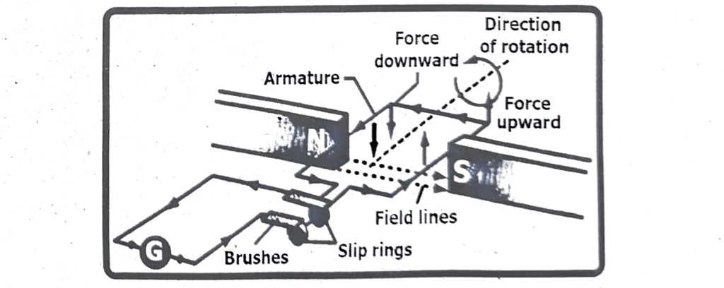
Q4. Define an alternating current (AC) generator. Draw a labeled diagram and explain its components and operation. How does it convert mechanical energy into electrical energy?
Alternating current (AC) generator:
An AC generator converts mechanical energy into electrical energy through electromagnetic induction. It works by rotating a coil of wire within a magnetic field, inducing an alternating current (AC) in the coil. Slip rings and brushes are used to maintain a continuous connection to the external circuit as the coil rotates.
Principle of alternating current (AC) generator:
An AC generator, or alternator, converts mechanical energy into electrical energy using the principle of electromagnetic induction, specifically Faraday’s Law.
Detailed explanation:
- Magnetic Field:
The generator utilizes a strong magnetic field, often created by permanent magnets or electromagnets.
- Rotating Coil (Armature):
A coil of wire, also known as the armature, is placed within this magnetic field.
- Mechanical Rotation:
External mechanical force, like from a turbine, rotates the coil.
- Electromagnetic Induction:
As the coil rotates, it cuts through the magnetic field lines, which induces a voltage (electromotive force or e. m. f.) across the coil. This is based on Faraday’s law of induction.
- Alternating Current (AC):
The direction of the induced voltage changes as the coil rotates, creating an alternating current in the coil and the external circuit.
- Slip Rings and Brushes:
Two slip rings are connected to the ends of the rotating coil. Brushes, typically made of carbon, press against the slip rings, providing a sliding electrical contact. This allows the current to flow from the rotating coil to the external circuit without the need for wires to twist and tangle.
In essence, the rotating coil creates a changing magnetic flux, which induces an (e. m. f) and drives the flow of alternating current in the circuit.
An AC generator converts mechanical energy into electrical energy through electromagnetic induction. A rotating coil (armature) within a magnetic field cuts across the magnetic field lines, inducing a voltage and current in the coil. This current alternates direction as the coil rotates, producing alternating current (AC).
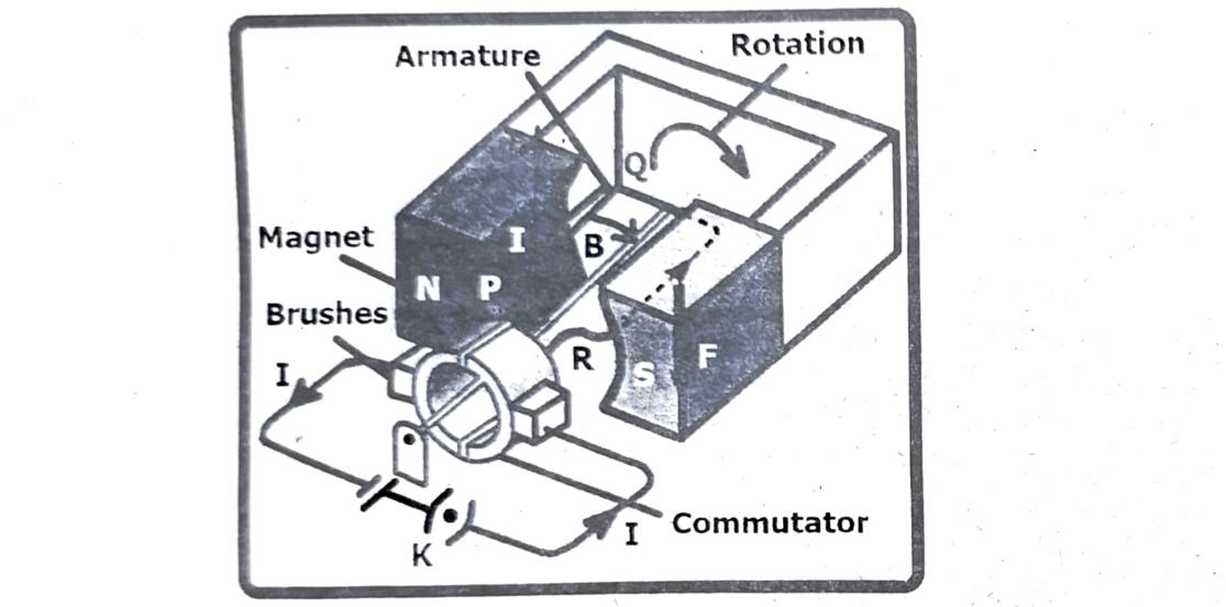
Q5. What is an AC motor? Draw a labeled diagram and explain its components and operation. How does it convert electrical energy into mechanical energy?
An electric motor converts electrical energy into mechanical energy, typically rotational motion, using the interaction of magnetic fields and electric currents. A split-ring commutator and brushes are essential components that enable the motor to rotate continuously by reversing the current direction in the coil every half turn.
An AC motor is an electric motor that operates on alternating current (AC). It primarily consists of a stator and a rotor. The stator is the stationary part with windings that create a rotating magnetic field when AC power is applied. The rotor, located inside the stator, experiences this rotating field and generates its own magnetic field, causing it to rotate and produce mechanical work.
Components of an AC Motor:
- Stator: The outer, stationary part of the motor containing windings that carry alternating current. These windings are arranged to create a rotating magnetic field when energized.
- Rotor: The rotating part of the motor, located inside the stator. It can be a squirrel cage (conductive bars shorted at both ends) or a wound rotor (with windings connected to slip rings).
- Bearings: Support the rotor and allow for smooth, low-friction rotation. They are typically made of high-quality materials like stainless steel or ceramic.
- Housing: Encloses all internal components, providing structural support and protection.
- Shaft: The rotating component that transmits mechanical power to the load.
How AC Motors Operate:
- Rotating Magnetic Field:
When AC voltage is applied to the stator windings, it creates a rotating magnetic field.
- Induced Current:
This rotating magnetic field induces a current in the rotor’s conductive elements (bars or windings).
- Torque Production:
The interaction between the stator’s rotating magnetic field and the rotor’s induced magnetic field generates torque, causing the rotor to spin.
- Continuous Rotation:
The rotor continues to rotate as long as the AC power supply is maintained and the rotating magnetic field interacts with the rotor’s magnetic field.
- Speed Control:
The speed of an AC motor is primarily determined by the frequency of the AC power supply and the number of poles in the motor.
Conversion of Electrical Energy into Mechanical Energy:
An AC motor converts electrical energy into mechanical energy through the interaction of magnetic fields. Alternating current (AC) flowing through the motor’s coils creates a rotating magnetic field, which then interacts with another magnetic field (either from permanent magnets or another set of electromagnets) in the rotor, causing it to rotate and produce mechanical motion.
Q6. Define a transformer. Explain its principle of operation, components, and applications. How does it change the AC voltage?
A transformer is a static electrical device that transfers electrical energy between two or more circuits through electromagnetic induction. It’s primarily used to change the voltage level of alternating current (AC) power, either increasing it (step-up) or decreasing it (step-down), while maintaining the frequency. This is achieved without any direct electrical connection between the circuits, relying instead on the principle of mutual inductance.
Principle of Operation:
Transformers operate based on the principle of electromagnetic induction and mutual inductance. When an alternating current flows through the primary winding, it creates a changing magnetic field in the core. This changing magnetic field then induces a voltage in the secondary winding, also creating an alternating current. The ratio of the number of turns in the primary and secondary windings determines the voltage transformation ratio.
Components of a Transformer:
- Core: Provides a low reluctance path for the magnetic flux to link the primary and secondary windings. Common core materials include iron or ferrite.
- Primary Winding: The coil of wire connected to the input AC voltage source.
- Secondary Winding: The coil of wire where the induced voltage appears.
- Insulation: Materials like insulating oil, tape, paper, or wood-based lamination, used to isolate the primary and secondary windings and prevent short circuits.
- Terminals: Connect the transformer to the external circuits.
- Cooling System: Depending on the size and power rating, transformers may have cooling systems like cooling fins or oil cooling systems to dissipate heat.
Applications of Transformers:
Transformers are essential components in power distribution and many electronic devices. They are used:
- In power grids: To step up voltage for efficient long-distance transmission and step-down voltage for local distribution and use.
- In electronic devices: To provide the appropriate voltage levels for various components.
- In power supplies: For converting AC voltage to DC voltage for powering electronic devices.
- In welding machines: To provide the high current required for welding.
How Transformers Change AC Voltage:
Transformers change AC voltage by altering the number of turns in the primary and secondary windings. The voltage is stepped up or down based on the turns ratio ($N_1/N_2$), where $N_1$ is the number of turns in the primary winding and $N_2$ is the number of turns in the secondary winding.
Step-up Transformer:
If $N_2 > N_1$, the secondary voltage ($V_2$) will be higher than the primary voltage ($V_1$).
Step-down Transformer:
If $N_2 < N_1$, the secondary voltage ($V_2$) will be lower than the primary voltage ($V_1$).
This change in voltage is achieved while maintaining the frequency of the AC power, thanks to the principles of electromagnetic induction and mutual inductance.