
Electric Current:
Electric current is the rate of flow of electric charge through a conductor. In simpler terms, it’s the amount of electric charge passing a point in a circuit per unit of time.
- Symbol: The symbol for electric current is usually $I$.
- Formula: Electric current ($I$) is defined as $I=\frac{Q}{t}$.
Where:
- $I$ is the electric current.
- $Q$ is the amount of electric charge that has passed through the conductor.
- $t$ is the time.
To calculate electric current:
If 10 coulombs of charge flow through a wire in 5 seconds, what is the electric current?
Solution:
$\Delta Q=10$, $\Delta t=5\,\text{s}$.
By using the formula: $I=\frac{\Delta Q}{\Delta t}=\frac{10}{5}=2\,\text{A}$.
Answer: The time rate of flow of electric charges through a cross-sectional area is called electric current.
Consider charge $\Delta Q$ flowing through any cross-sectional area in time $\Delta t$, as shown in figure. The electric current $I$ will then be given by:
$$I=\frac{\Delta Q}{\Delta t}$$
The SI unit of current is the ampere, which is denoted by (A). One ampere current in terms of flow of charge is stated as “when one coulomb of charge flows through any cross-sectional area in one second”.
Mathematically: $1\,\text{A}=\frac{1\,\text{C}}{1\,\text{s}}$.
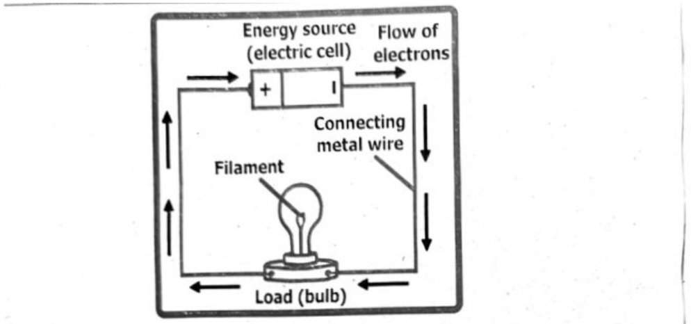
Ampere is a large unit of electric current, that’s why the following sub-multiples of ampere are most commonly used:
- 1 milliampere = 1 mA = $10^{-3}$ A
- 1 microampere = 1 μA = $10^{-6}$ A
Electrical Conduction in Metals:
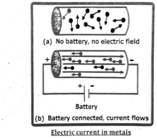
Electrical conduction in metals is explained by the movement of free electrons. These electrons, loosely held by the metal atoms, are able to move freely throughout the metal’s structure when a voltage is applied, creating an electric current.
Detailed Explanation:
Free Electrons:
Metals have a “sea” of valence electrons that are not tightly bound to individual atoms. These electrons are free to move throughout the metallic structure.
Applying a Voltage:
When a voltage (or electric field) is applied to a metal, it creates an electric field that exerts a force on these free electrons.
Electron Movement:
The electric field causes the free electrons to drift in a direction opposite to the field’s direction, creating an electrical current.
Collisions:
As electrons move, they collide with the metal ions (the remaining positively charged atoms) and other electrons, causing them to change direction and slow down.
Drift Velocity:
Despite these collisions, the electrons have an overall drift velocity in the direction of the applied electric field.
Current:
The movement of these charged particles (electrons) constitutes an electric current, and the rate of flow of charge is what we measure as current.
Good Conductors:
Metals are good conductors because they have a large number of free electrons that are readily available to carry the electrical current.
Electric current is indeed measured in amperes, often shortened to amps. One ampere (1 A) is defined as the flow of one coulomb (C) of electric charge passing a point in a circuit per second (1 C/s). Therefore, 1 amp is equivalent to 1 coulomb per second.
Hence, 1 Ampere = 1 Coulomb / second (C/s)
Difference between direct current (d.c.) and alternating current (a.c.):
| Feature | Direct Current (DC) | Alternating Current (AC) |
|---|---|---|
| Direction of Flow | Flows in one constant direction | Reverses direction periodically |
| Source | Batteries, solar cells, DC generators | Power stations, AC generators |
| Waveform | Straight line (constant voltage) | Sine wave (commonly), can be square or triangular |
| Voltage Level | Constant | Varies with time |
| Frequency | 0 Hz | 50 Hz (Europe, Asia), 60 Hz (USA) |
| Transmission | Not efficient over long distances | More efficient for long-distance transmission |
| Use in Devices | Used in electronic devices (phones, laptops, etc.) | Used in home appliances, factories, and power grids |
| Conversion | Can be converted to AC using an inverter | Can be converted to DC using a rectifier |
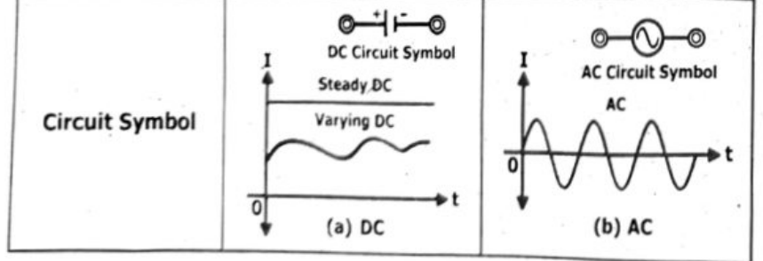
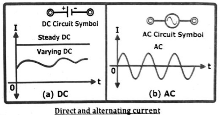
| Circuit Symbol | DC Circuit Symbol; Steady DC; Varying DC; (a) DC | AC Circuit Symbol; AC; (b) AC |
OR (Second Answer)
Direct current (DC) flows in a single direction, while alternating current (AC) periodically reverses direction. In DC, the voltage and current remain relatively constant, whereas in AC, they fluctuate over time, cycling between positive and negative values.
Here’s a more detailed breakdown:
Direct Current (DC):
- Flow of Electrons: Electrons flow in one direction, from the negative terminal to the positive terminal of a power source.
- Voltage and Current: DC voltage and current are generally constant and do not change direction.
- Examples: Batteries, solar panels, and electronic devices often use DC power.
- Applications: DC is well-suited for portable devices, electronics, and applications where energy storage is needed (e.g., batteries).
Alternating Current (AC):
- Flow of Electrons: Electrons flow in one direction, then reverse and flow in the opposite direction, repeating this cycle periodically.
- Voltage and Current: AC voltage and current change direction, typically following a sinusoidal (wave-like) pattern.
- Examples: Mains electricity (household power outlets) and power grids utilize AC.
- Applications: AC is preferred for transmitting electrical power over long distances due to its ability to be easily transformed to different voltage levels.
Alternating current at high voltage (above 500 V) is more dangerous than direct current at the same voltage. When a person touches a high-voltage DC source, it usually causes a single muscle contraction that can be strong enough to push the person away from the source. By contrast, touching a high-voltage AC source can cause a continuing muscle contraction that prevents the victim from letting go of the source.
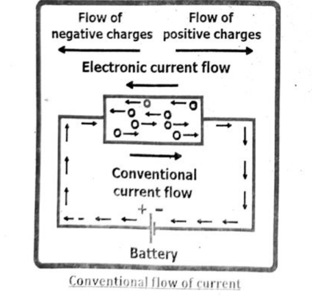
The key difference between conventional and actual (or electron) current lies in the direction of charge flow. Conventional current is defined as the flow of positive charge from the positive terminal to the negative terminal of a power source, while actual (or electron) current is the flow of negative charge (electrons) from the negative terminal to the positive terminal. While conventional current is a historical convention, electron current reflects the physical reality of charge movement in most circuits.
| Aspect | Conventional Current | Actual Current |
|---|---|---|
| Direction of Flow | From positive terminal to negative terminal | From negative terminal to positive terminal |
| Type of Charge Flow | Imaginary flow of positive charges | Actual flow of negative charges (electrons) |
| Used In | Circuit diagrams and theoretical analysis | Physical and real-world behavior of electric circuits |
| Simplicity | Easier to conceptualize and apply in circuit analysis and design. | Harder to visualize because it goes against the assumed direction in most diagrams. |
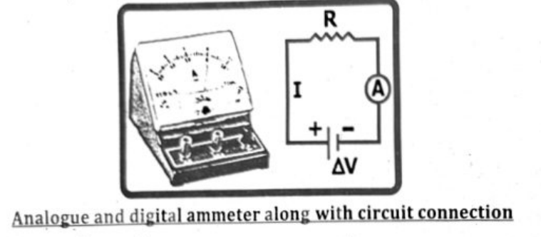
AMMETER:
An ammeter is a device used to measure electric current, which is the flow of electrical charge. To accurately measure current, an ammeter is connected in series within the circuit, meaning the current being measured must flow directly through the ammeter. It is crucial for an ammeter to have a very low resistance to minimize its impact on the circuit’s current flow.
Digital vs. Analog:
Ammeters come in both digital and analog (needle-based) forms. Digital ammeters offer precise readings and often have features like auto-ranging, while analog ammeters provide a visual indication of current changes.
Analog Ammeters:
- Mechanism: Analog ammeters typically use a coil of wire that is deflected by the magnetic field generated by the current being measured. A needle attached to the coil moves across a calibrated scale, indicating the current value.
- Features: They are known for their simplicity, robustness, and ability to provide a visual indication of current fluctuations. Analog ammeters are often favored for applications where real-time monitoring and quick visual assessment are important.
- Ranges: Analog ammeters can be designed with a wide range of scales to accommodate different current levels. They may utilize shunts (resistors) to extend their measuring range.
- Example: An analog ammeter might be used in a laboratory setting to measure the current in a circuit, with a scale indicating the current in amps or milliamps.
Digital Ammeters:
- Mechanism: Digital ammeters use a combination of a shunt resistor, an analog-to-digital converter (ADC), and a digital display to indicate the current.
- Features: They offer greater precision and accuracy in readings compared to analog ammeters. Digital displays make it easy to read the current value, and some digital ammeters may also offer additional features like data logging or connectivity.
- Ranges: Digital ammeters also come in various ranges, allowing them to measure both low and high currents. The ranges can be selected manually or automatically, depending on the device.
Example: A digital ammeter might be used to measure the current in a power supply circuit, with the display showing the current value to several decimal places.
Range of ammeter: Generally ammeters of different ranges are used based on the amount of current in the circuit. When you are measuring current in your home appliances, usually an ammeter with ampere values ranging from 1 A to 100 A is used. For small currents we use milli-ammeter (mA) or micro-ammeter (μA).
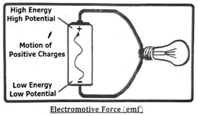
Ans: Electromotive force (e.m.f) is the electrical work done by a source (like a battery or generator) in moving a unit charge around a complete circuit. It's defined as the energy provided by the source per unit charge.
- The formula for (e.m.f) is $E = W/Q$, where $E$ is (e.m.f) in volts, $W$ is the work done in joules, and $Q$ is the charge in coulombs.
- It's essentially the “push” that causes charge to flow. (e.m.f) is measured in volts and is often denoted by the symbol ‘e’ or ‘E’. (e.m.f) is measured in volts (V), which is equivalent to joules per coulomb (J/C).
Explanation:
Work done by a source:
When a charge moves through a circuit, the source (e.g., a battery) does work on it, providing energy to overcome resistance and keep the current flowing.
- Unit charge: e.m.f focuses on the work done on a single unit of charge (e.g., one coulomb).
- Complete circuit: The charge is considered to move all the way around the circuit, from one terminal of the source, through all the components, and back to the starting terminal.
- Equation: The formula $E = W/Q$ directly relates (e.m.f) to the work done and the charge moved.
Ans: Electroencephalography (EEG) is a neurological test that uses electronic monitoring device to measure and record the electrical activity of brain. To record the electrical activity of the brain, 8 to 16 pairs of electrodes are attached to the scalp. Each pair of electrodes transmits a signal to one of several recording channels of the electroencephalograph. This signal consists of the difference in the voltage between each pair of electrodes. The rhythmic fluctuation of this potential difference is shown through graph by the recording channel.
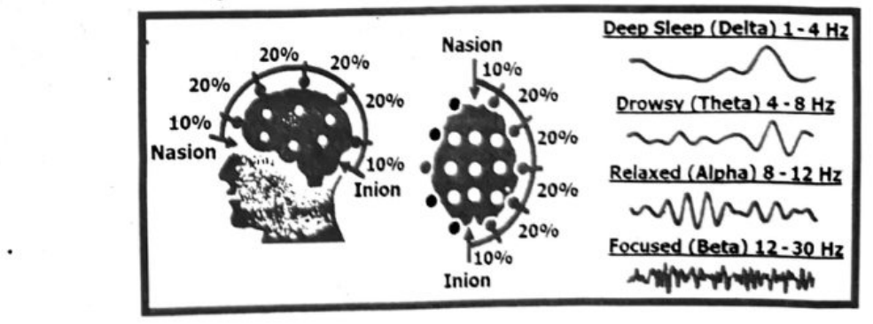
The SI unit of electromotive force is the same as that of electric potential: $\mathrm{J/C = V}$. Examples of e.m.f. sources are batteries (converting chemical energy into electrical energy), solar panels (solar to electrical), thermocouples (thermal to electrical) and generators (mechanical to electrical).
Potential difference (p.d.):
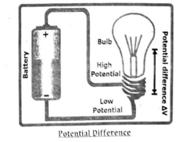
Potential difference is the amount of work energy required to move an electric charge from one point to another. The unit of potential difference is the volt.
The potential difference across a component in a circuit is defined as:
The energy transferred per unit charge flowing from one point to another.
- Potential difference (sometimes called voltage) is measured in volts (V). One volt is the same as one joule per coulomb ($\mathrm{J\ C^{-1}}$).
- If a bulb has a potential difference of 3 V, every coulomb of charge passing through the bulb will transfer 3 J of energy to the bulb.
- The potential difference of a power supply connected in series is always shared between the components in the circuit.
Formula: $V = W/Q$, where $V$ is potential difference, $W$ is work done and $Q$ is charge.
Example 1: Finding potential difference
If 50 joules of energy are used to move 10 coulombs of charge through a resistor, what is the potential difference across the resistor?
Using the formula $V = W/Q$:
$V = 50\ \mathrm{J} / 10\ \mathrm{C}$
$V = 5$ volts
Example 2: Finding work done
If the potential difference across a light bulb is 12 volts and 2 coulombs of charge pass through it, how much work is done?
Rearranging the formula to $W = VQ$:
$W = 12\ \mathrm{V} \times 2\ \mathrm{C}$
$W = 24$ joules
Example 3: Finding charge
If 100 joules of work are done across a potential difference of 20 volts, what is the amount of charge that has moved?
Rearranging the formula to $Q = W/V$:
$Q = 100\ \mathrm{J} / 20\ \mathrm{V}$
$Q = 5$ coulombs
Both electromotive force (e.m.f.) and potential difference (p.d.) are measured in volts, which is equivalent to joules per coulomb (J/C). A volt represents the amount of energy (in joules) transferred to each unit of electric charge (in coulombs) as it moves through a circuit or a component within a circuit.
Detailed explanation:
- e.m.f.: Is the energy supplied by a source (like a battery or generator) to move a unit of electric charge around a complete circuit.
- Potential Difference (PD): Is the energy transferred by a charge as it moves between two points in a circuit.
- Volt: Is the unit of both e.m.f. and PD. Volt is defined as the potential difference between two points when one joule of energy is used to move one coulomb of charge from one point to the other. The relationship can be expressed as:
1 Volt = 1 Joule / Coulomb (1V = 1 J / C)
$\Delta V = \frac{\Delta U}{\Delta q} = \frac{\Delta W}{\Delta q}$
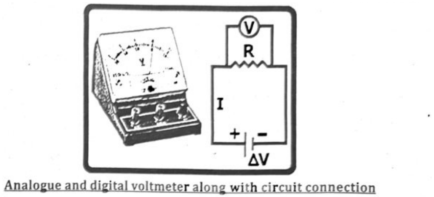
Voltmeters are used to measure the electrical potential difference (voltage) between two points in a circuit. They can be either analog, using a needle to indicate voltage, or digital, displaying the voltage numerically. Both types come in various ranges to accommodate different voltage levels, from fractions of a volt to thousands of volts.
Analog Voltmeters:
- Mechanism: Analog voltmeters utilize a moving coil galvanometer with a series resistor to indicate voltage. The pointer deflection is proportional to the voltage across the circuit.
- Display: They present voltage readings using a needle that moves across a calibrated scale.
- Ranges: Analog voltmeters often have multiple ranges selected by a switch, allowing measurement of different voltage levels. For example, a meter might have ranges of 1 V, 10 V, and 100 V.
- Accuracy: Accuracy is typically expressed as a percentage of the full-scale reading. For example, an analog voltmeter with a 2% accuracy on a 10 V scale might have an error of ± 0.2 V at a reading of 5 V.
- Applications: Analog voltmeters are used in various applications, including electronics repair, power generation, and automotive maintenance.
Digital Voltmeters:
- Mechanism: Digital voltmeters convert the analog voltage signal into a digital value using an analog-to-digital converter (ADC).
- Display: They present voltage readings on a digital display as numerical values.
- Ranges: Digital voltmeters also have multiple ranges, often with automatic range selection, making them more versatile.
- Accuracy: Digital voltmeters generally offer higher accuracy than analog meters, with accuracies often better than 1%.
- Applications: Digital voltmeters are widely used in various fields, including electronics, electrical engineering, and scientific research.
Examples of Range Selection:
- Low Voltage: A low-voltage voltmeter might have ranges like 0 - 2 V, 0 - 20 V, and 0 - 200 V for measuring small voltages in electronic circuits.
- High Voltage: High-voltage voltmeters are designed for measuring voltages in power systems, potentially ranging from 0 - 1 kV, 0 - 10 kV, and even higher.
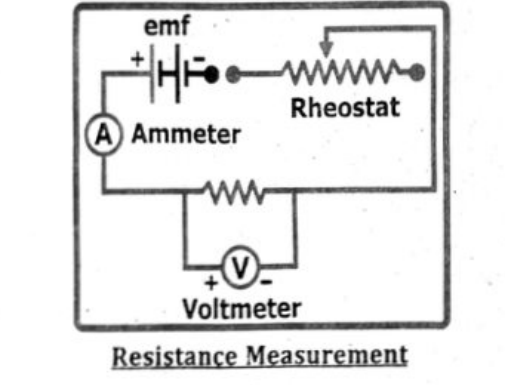
To determine the resistance of a component using a voltmeter and ammeter, connect the ammeter in series with the component and the voltmeter in parallel across the component. Measure the voltage ($V$) across the component and the current ($I$) flowing through it. Then, calculate the resistance ($R$) using Ohm's law: $R = V / I$.
Detailed Procedure:
- Circuit Setup:
- Connect the ammeter in series with the component (e.g., a resistor) whose resistance you want to measure.
- Connect the voltmeter in parallel with the component.
- Include a power supply (or battery) and a variable resistor (rheostat) in the circuit to control the voltage and current.
- A switch can be included to control the flow of current and prevent heating of components.
- It’s recommended to start with the variable resistor at its maximum resistance to limit the initial current.
- Taking Measurements:
- Close the switch to complete the circuit.
- Adjust the variable resistor to obtain a suitable range of voltage and current readings.
- Record the voltage reading from the voltmeter and the current reading from the ammeter.
- Ensure the voltmeter and ammeter are set to appropriate ranges for accurate readings.
- It is advisable to take multiple readings by varying the voltage with the rheostat to ensure accuracy.
(iii) Calculations:
- Use Ohm's law to calculate the resistance ($R$) for each set of voltage ($V$) and current ($I$) readings: $R = V/I$.
- You can then calculate an average resistance from the multiple readings.
Note: The ammeter should ideally have a very low resistance, and the voltmeter should ideally have a very high resistance to minimize their impact on the circuit.
The experimental setup for finding an unknown resistance is shown in the figure. The unknown resistance is connected in series with the ammeter while the voltmeter is connected in parallel with the unknown resistance. A variable resistance called rheostat is also connected in series with the unknown resistance and ammeter. Ensure the indicators on both the voltmeter and the ammeter align with the zero mark on their scales.
| Sr. No. | Ammeter Reading (A) | Voltmeter Reading (V) | Resistance ($R=V/I$) |
|---|---|---|---|
| 1. | 0.20 A | 1.00 V | $1.00/0.20 = 5.00\ \Omega$ |
| 2. | 0.30 A | 1.50 V | $1.50/0.30 = 5.00\ \Omega$ |
| 3. | 0.40 A | 2.00 V | $2.00/0.40 = 5.00\ \Omega$ |
| 4. | 0.50 A | 2.50 V | $2.50/0.50 = 5.00\ \Omega$ |
Ans: Resistivity ($\rho$) is a material property that describes how strongly a material opposes the flow of electric current.
- The resistance ($R$) of a material is directly proportional to its resistivity ($\rho$) and length ($L$), and inversely proportional to its cross-sectional area ($A$). The formula is $R = \rho\frac{L}{A}$.
- Resistivity ($\rho$): A material property that indicates how strongly a material opposes the flow of electric current.
- Length ($L$): The longer the conductor, the greater the resistance.
- Cross-sectional area ($A$): The larger the area, the lower the resistance.
The relationship between resistance ($R$), resistivity ($\rho$), length ($L$), and cross-sectional area ($A$) is given by the following formula:
$$R \propto \frac{L}{A} \qquad \text{or} \qquad R = \rho\frac{L}{A}$$
Whereas ‘$\rho$’ is proportionality constant and is called resistivity of the material. Mathematically:
$$\rho = R\frac{A}{L}$$
The unit of resistivity is ohm–m ($\Omega\,\mathrm{m}$).
Specific resistance or resistivity ($\rho$) of a material is the resistance offered by a wire of length 1 m having cross-sectional area 1 m$^2$.
Good electric conductors have very low resistivities, and good insulators have very high resistivities.
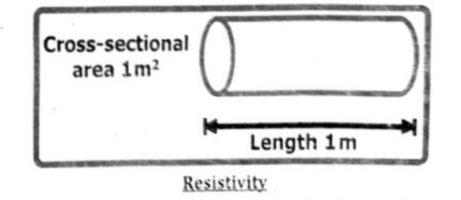
The resistivity of metals and alloys is very small; therefore, they are very good conductors of electricity. On the other hand, the resistivity of insulators is very high, which is why they conduct current with difficulty.
Whereas the resistivity of semiconductors lies between that of conductors and insulators. By doping semiconductors (introducing controlled amounts of impurities), their resistivities can be changed dramatically, which is one reason semiconductors are used to make computer chips and other electronic devices.
TEMPERATURE DEPENDENCE OF RESISTIVITY
The resistance of every conductor varies with temperature. At higher temperatures, the internal energy of the material increases, causing the positive ions to vibrate with greater amplitudes. This increased vibration leads to more frequent collisions between electrons and ions.
Consequently, the motion of electrons is hindered, reducing the current for a given electric field. This phenomenon explains why the resistivity of metals typically increases with rising temperature.
Consider a conductor having resistivity $\rho_0$ at 0°C and $\rho_T$ at T°C. It is found that for normal temperatures the change in resistivity, $\Delta\rho = \rho_T - \rho_0$, is directly proportional to:
- Initial resistivity $\rho_0$: $\rho_T - \rho_0 \propto \rho_0$ (i)
- Rise in temperature $T$: $\rho_T - \rho_0 \propto \Delta T$ (ii)
Combing proportionalities in (i) and (ii), we get:
$$\rho_T - \rho_0 \propto \rho_0\Delta T$$
Changing the sign of proportionality into equality, we get:
$$\rho_T - \rho_0 = \alpha\rho_0\Delta T$$
When ‘$\alpha$’ is the constant of proportionality and is called temperature coefficient of resistivity. Its value depends only upon the nature of material.
Mathematically, $\displaystyle \alpha = \frac{\rho_T - \rho_0}{\rho_0\Delta T}$
The units of temperature coefficient of resistance or resistivity are °C⁻¹ or K⁻¹. For common metals, ‘$\alpha$’ typically has a value of 0.003 to 0.005 °C⁻¹. That is, an increase in temperature of 1C° increase the resistance by 0.3% to 0.5%.
The resistivity of a metallic conductor nearly always increases with increasing temperature; this relationship is quantified by the temperature coefficient of resistivity, which is positive for metals.
Interestingly, the temperature coefficient of resistivity is negative for semiconducting materials. This means that, unlike metals, the resistivity of semiconductors decreases with increasing temperature.
Ans: Ohm’s Law states that the current ($I$) flowing through a conductor is directly proportional to the voltage ($V$) across its ends and inversely proportional to the resistance ($R$), provided the temperature remains constant.
If ‘$V$’ is the potential difference across the two ends of a conductor, then current ‘$I$’ will flow through it. Mathematically:
$$I \propto V \quad (\text{Temperature } T = \text{Constant})$$
Replacing sign of proportionality with equality and putting a constant:
$$I = \frac{V}{R} \quad \text{or} \quad V = IR$$
Example:
- Voltage ($V$) = 10 V
- Resistance ($R$) = 5 Ω
- Current ($I$) = ?
$$I = \frac{V}{R} = \frac{10}{5} = 2\text{ A}$$
Ohm’s law essentially describes how voltage, current, and resistance are related in a simple electrical circuit. It states that if you increase the voltage across a conductor, the current will increase proportionally, assuming the resistance remains constant. Conversely, if you increase the resistance, the current will decrease, again assuming constant voltage.
Applying Ohm’s Law (Examples):
Problem: A resistor has a voltage of 12 V and a current of 2 A flowing through it. What is the resistance?
Solution: Using the formula $R = V/I$, we get $R = 12\text{ V} / 2\text{ A} = 6$ ohms.
Problem: A circuit has a 10-ohm resistor and a voltage source of 5 V. What is the current flowing through the resistor?
Solution: Rearranging the formula to $I = V/R$, we get $I = 5\text{ V} / 10\text{ ohms} = 0.5\text{ A}$.
Problem: If the voltage across a 4-ohm resistor is doubled, what happens to the current?
Solution:
Since current is directly proportional to voltage (at constant resistance), doubling the voltage will also double the current. If the initial current was ‘$x$’, the new current will be ‘$2x$’.
Limitations of ohm’s law:
- Not valid for non-ohmic materials: (like diodes, transistors).
- Fails at high voltages and temperatures: resistance may change.
- Doesn’t apply to non-linear circuits: where current doesn’t vary linearly with voltage.
- Only applies to metallic conductors: not semiconductors or insulators.
- Ignores frequency effects – not suitable for AC circuits with inductance / capacitance.
Difference between ohmic and non ohmic devices:
| Feature | Ohmic Devices | Non-Ohmic Devices |
|---|---|---|
| Obeys Ohm’s Law | Yes – $V \propto I$ (voltage is directly proportional to current) | No – $V$ and $I$ are not proportional |
| Resistance | Constant | Varies with voltage or current |
| V-I Graph | Straight line through the origin | Curved or nonlinear graph |
| Examples | Resistors, metallic wires (like copper, aluminum) | Diodes, transistors, thermistors, filament lamps |
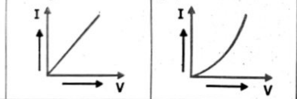
When the temperature of a resistor increases, its resistance also increases. This happens because the atoms in the conductor vibrate more at higher temperatures, causing more collisions with the flowing electrons. These collisions make it harder for the electrons to move, which increases the resistance. Therefore, as temperature rises, the flow of current becomes less efficient in most metallic resistors.
OR (Second Answer)
Generally, increasing the temperature of a resistor will increase its resistance for most metallic conductors. This is because higher temperatures cause the atoms within the resistor material to vibrate more vigorously, disrupting the flow of electrons and thus increasing resistance. However, this relationship is not universal, and some materials like semiconductors show a decrease in resistance with increasing temperature.
Types of resistor:
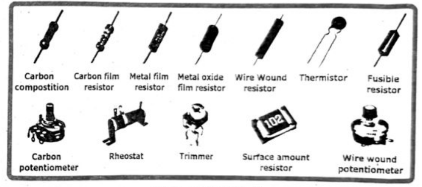
OHMIC AND NON-OHMIC DEVICES:
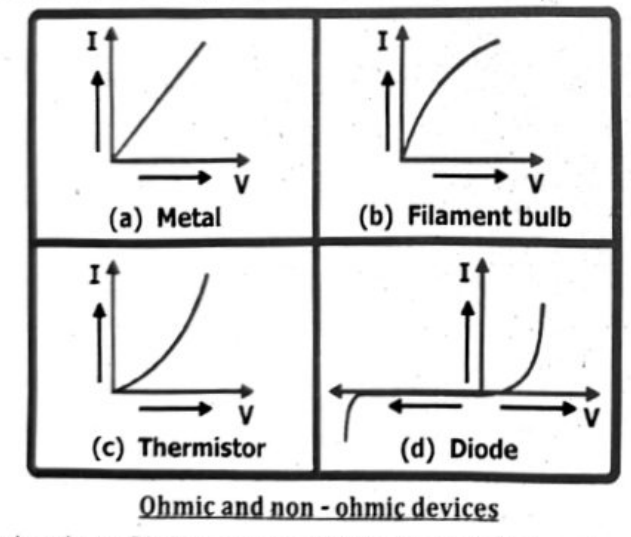
Current-voltage ($I-V$) graphs visually represent the relationship between current and voltage in an electrical circuit for a specific component. The shape of the graph reveals key information about the component’s behavior and its resistance.
Ohmic Conductors:
For materials like resistors, the $I-V$ graph is a straight line, indicating a constant resistance. This means that as voltage increases, the current increases proportionally.
Non-Ohmic Conductors:
Some materials, like diodes or filament lamps, do not exhibit a linear relationship between voltage and current. Their $I-V$ graphs will be curved, showing that resistance changes with voltage or current.
Interpreting the Slope:
The slope of the $I-V$ graph is calculated as change in current ($\Delta I$) divided by change in voltage ($\Delta V$), which is equivalent to $1/\text{resistance}$ ($1/R$). A steeper slope (greater change in current for a given change in voltage) indicates a lower resistance, and a shallower slope indicates a higher resistance.
Verification:
To verify if a material obeys Ohm’s Law, plot its $I-V$ graph. If the graph is a straight line passing through the origin, the material follows Ohm’s Law.
Example:
A filament lamp, which is a non-ohmic conductor, shows a curved $I-V$ graph. As the voltage increases, the filament heats up, increasing its resistance, and causing the current to increase at a slower rate.
Ohmic and non - ohmic devices
Semiconductor Diode graph also deviates very strictly from the straight line voltage ‘V’ and current ‘I’ relationship. In fact most modern electronic devices, such as transistors, have nonlinear current-voltage relationships; therefore they are non-ohmic.
Examples:
GIVEN:
Current $I = 10.0\ \mathrm{A}$
Time $\Delta t = 2\ \mathrm{hr} = 2 \times 3600\ \mathrm{s} = 7200\ \mathrm{s}$
REQUIRED:
Charge $\Delta Q = ?$
SOLUTION:
By definition of electric current: $I = \frac{\Delta Q}{\Delta t}$ or $\Delta Q = I \times \Delta t$
Putting values: $\Delta Q = 10.0\ \mathrm{A} \times 7{,}200\ \mathrm{s}$
Therefore, $\Delta Q = 72{,}000\ \mathrm{C}$ [ANSWER]
Which is equal to 20 Ah, a most commonly used specification for batteries.
GIVEN:
Potential difference $V = 2 \times 1.5\ \mathrm{V} = 3.0\ \mathrm{V}$
Resistance $R = 20.0\ \Omega$
REQUIRED:
Current $I = ?$
SOLUTION:
By Ohm’s law: $V = IR$ or $I = \frac{V}{R}$
Putting values: $I = \frac{3.0\ \mathrm{V}}{20\ \Omega}$
Therefore, $I = 0.15\ \mathrm{A} = 150\ \mathrm{mA}$ [ANSWER]
Thus, a current of 0.15 A pass through the circuit of torch.
GIVEN:
- Potential difference $V = 12.0\ \mathrm{V}$
- Current $I = 200\ \mathrm{mA} = 200 \times 10^{-3}\ \mathrm{A}$
REQUIRED:
Resistance $R = ?$
SOLUTION:
By definition of resistance: $R = \frac{V}{I}$
Putting values: $R = \frac{12.0\ \mathrm{V}}{200 \times 10^{-3}\ \mathrm{A}}$
Therefore, $R = 60\ \Omega$ [ANSWER]
So, the device connected in the circuit has 60 ohms resistance.
GIVEN:
- Length of silver wire $L = 1\ \mathrm{m}$
- Cross-section area $A = 0.4\ \mathrm{cm}^2 = 0.4 \times 10^{-4}\ \mathrm{m}^2$
- Resistivity of silver $\rho = 1.6 \times 10^{-8}\ \Omega\,\mathrm{m}$
REQUIRED:
Resistance $R = ?$
SOLUTION:
The relation for resistance is: $R = \frac{\rho L}{A}$
Putting values: $R = \frac{(1.6 \times 10^{-8}\ \Omega\,\mathrm{m})(1\ \mathrm{m})}{0.4 \times 10^{-4}\ \mathrm{m}^2}$
Therefore, $R = 4 \times 10^{-4}\ \Omega = 0.4\ \mathrm{m}\Omega$ [ANSWER]
So, the given silver wire will have a resistance of 0.4 mΩ.
GIVEN:
- Initial resistivity $\rho_0 = 5.6 \times 10^{-8}\ \Omega\,\mathrm{m}$
- Temperature difference $\Delta T = 30\ \mathrm{K}$
- Temperature co-efficient of resistivity $\alpha = 0.0045\ \mathrm{K}^{-1}$
REQUIRED:
Final resistivity $\rho_T = ?$
SOLUTION:
The temperature coefficient of resistivity is:
$$\alpha = \frac{\rho_T - \rho_0}{\rho_0\Delta T} \quad \text{or} \quad \rho_T = \rho_0(1 + \alpha\Delta T)$$
Putting values: $\rho_T = (5.6 \times 10^{-8}\ \Omega\,\mathrm{m})\{1 + (0.0045)(30\ \mathrm{K})\}$
Therefore, $\rho_T = 6.3 \times 10^{-8}\ \Omega\,\mathrm{m}$ [ANSWER]
So, the resistivity of the metallic conductor will become $6.3 \times 10^{-8}\ \Omega\,\mathrm{m}$ when the temperature is raised by 30 K.
Summary
- Electric Current is the rate of flow of charges.
- Ampere is the unit of electric current and is defined as one coulomb charge per second.
- Conventional Current is the direction of flow of positive charges per unit time.
- DC is the type of electric current that is unidirectional and does not change its direction.
- AC is the type of electric current which changes its direction continuously.
- Potential Difference is the amount of work done in moving a unit positive charge from one point to another inside an electric field.
- e.m.f. Source is any device that converts non-electrical energy into electrical energy.
- Ohm’s Law states that the amount of electric current in a circuit depends upon the potential difference while keeping temperature constant.
- Resistance is the opposition to the flow of charges or opposition to electric current.
- Resistivity is the resistance of unit length and unit area.
- Temperature Coefficient of Resistance is a measure of how a material’s resistance changes with temperature.
- Ammeter is a device used to measure electric current through any device.
- Voltmeter is a device used to measure potential difference across any device.